Refuse landfill seepage-proofing guide drainage system structure and laying method thereof

A landfill and system structure technology, applied in the field of landfill anti-seepage and drainage system structure, to achieve good chemical stability, strong tear and puncture resistance, and easy operation

Inactive Publication Date: 2014-06-04
HANGZHOU QIANXI ENVIRONMENTAL PROTECTION SCI & TECH
View PDF4 Cites 14 Cited by
  • Summary
  • Abstract
  • Description
  • Claims
  • Application Information

AI Technical Summary

Problems solved by technology

[0006] The invention provides a structure and method of an anti-seepage and drainage system of a garbage landfill, which has good mechanical strength, tear resistance and puncture resistance, and can solve the damage caus

Method used


Image

  • Refuse landfill seepage-proofing guide drainage system structure and laying method thereof
  • Refuse landfill seepage-proofing guide drainage system structure and laying method thereof
  • Refuse landfill seepage-proofing guide drainage system structure and laying method thereof

Examples


Embodiment 1

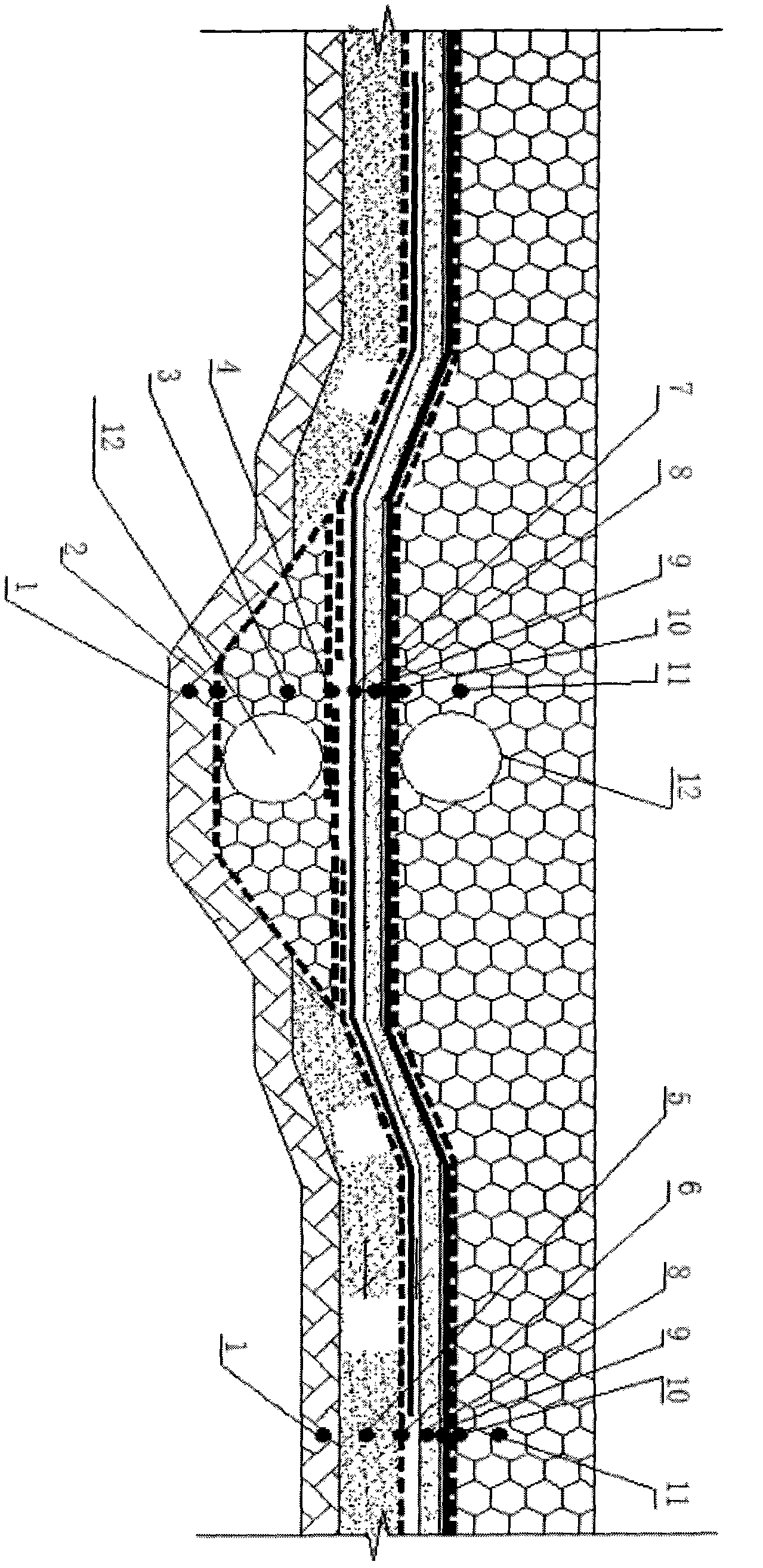
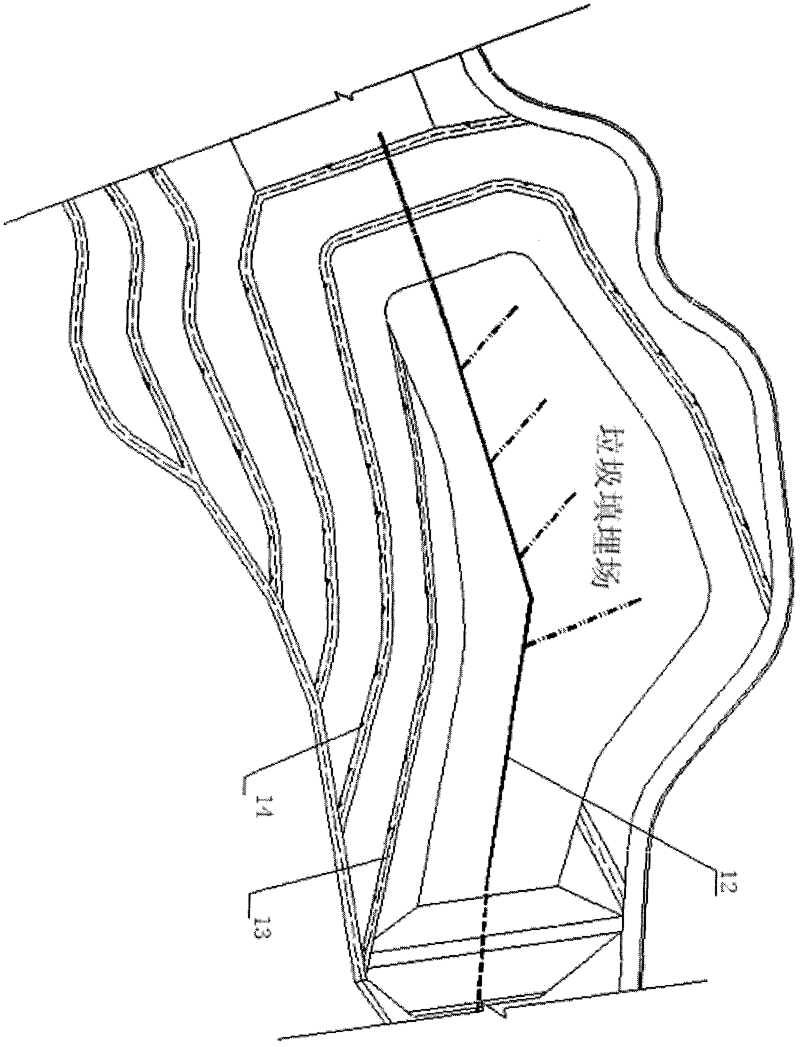
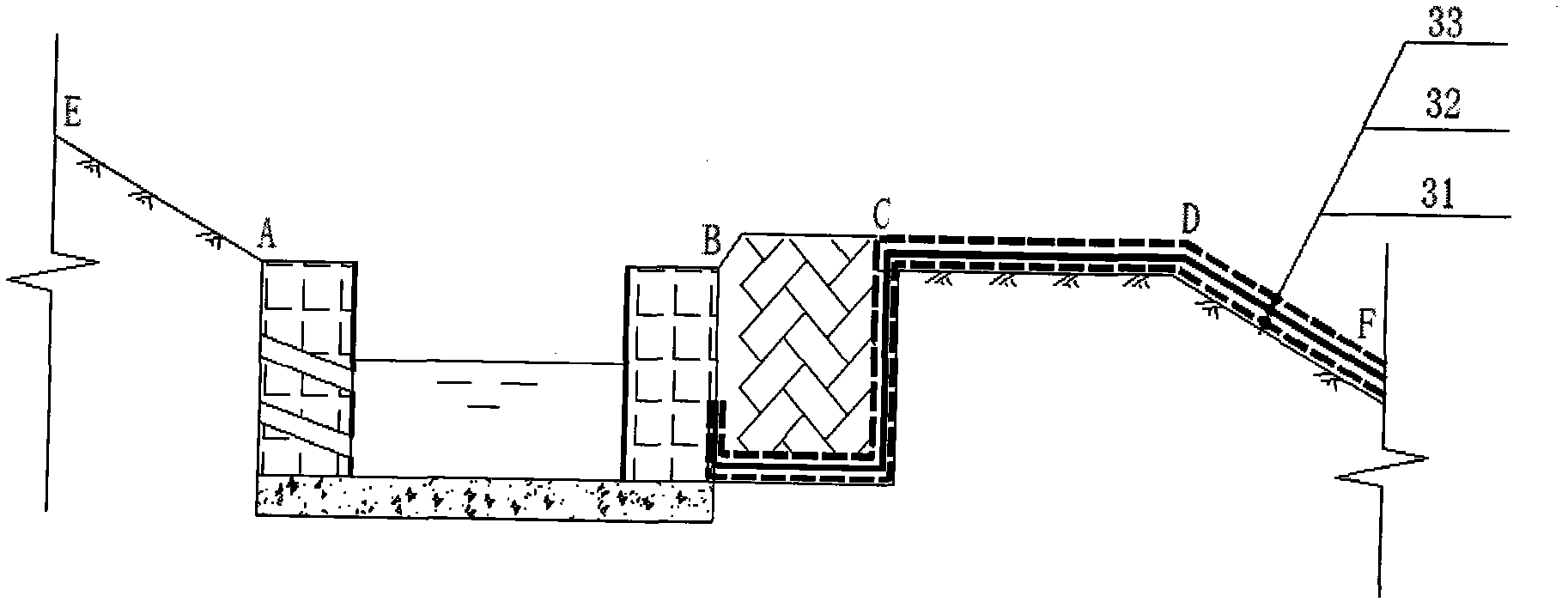
[0058] A landfill project, the project is an expansion project, the existing storage capacity is 1.3 million m 3 , the new storage capacity is 3 million m 3 , and the designed service life is fifteen years. The total area of ​​HDPE geomembrane, HDPE flower tube, GCL bentonite pad and non-woven geotextile anti-seepage and drainage system in the landfill area is 72664m 2 , the height of the slope in the landfill area is 20-64m, and the construction time of the anti-seepage system is two months. During the construction of this construction method, an operation group of 5-8 people can lay 1500-2000m per day 2 , the construction speed is fast and the quality is reliable, effectively solving the problems of secondary environmental pollution caused by leachate leakage caused by unreasonable anti-seepage and drainage treatment during the long-term use of the landfill, ensuring the quality of production and living water for the surrounding people , which saves the cost of environmen...

Embodiment 2

[0060] A domestic waste landfill project. The area of ​​the anti-seepage and drainage system in the landfill area is 160,000m 2 , the slope height of the waste landfill reservoir area is 25-60m, and the construction time of the anti-seepage and drainage system is six months. An operation group with 5-8 people can lay 1500m per day 2 It is safe and convenient to operate and reliable in quality. It effectively solves the secondary pollution of drinking water and cultivated land for surrounding people caused by leachate leakage, and ensures the physical and mental health of the people. It has significant social and economic benefits.


PUM

PropertyMeasurementUnit
Densityaaaaaaaaaa
Thicknessaaaaaaaaaa
Thicknessaaaaaaaaaa

Abstract

The invention discloses a refuse landfill seepage-proofing guide drainage system structure and a laying method thereof. An independent closed flexible reservoir-shaped seepage-proofing layer is composed of an HDPE geomembrane, a GCL (geosynthetic clay liner), a non-woven geotechnical cloth and the like, the seepage-proofing layer is provided with macadam, coarse sand and an HDPE floral tube to form a guide drainage structure for conducting guide drainage of landfill leachate and underground water, and a landfill reservoir base layer and the seepage-proofing guide drainage system structure are made stable, wherein anchoring measures are used for the guide drainage process. A double-slit sweat soldering process is mainly used for the HDPE geomembrane, and a single-slit extrusion soldering process is supplemented. A holt melting butt joint mode is used for the HDPE floral tube, a lap joint mode is used for the GCL, and a heat bonding lap joint mode is used for the non-woven geotechnical cloth. The refuse landfill seepage-proofing guide drainage system structure and the laying method thereof can solve the problems that secondary pollution happens due to the fact that refuse landfill leachate permeates into a subterranean layer, and a basement is damaged due to accumulation of the underground water. The refuse landfill seepage-proofing guide drainage system structure has very high seepage-proofing capacity, the permeability coefficient reaches 1.0*10<-11> cm/s, long-term stability is achieved, erosion can not happen, and the natural aging life is more than 50 years.

Description

technical field [0001] The invention relates to an anti-seepage and drainage system structure of a garbage landfill site and a construction method of the structure, belonging to the technical field of environmental engineering. Background technique [0002] The landfill is a reservoir area where the garbage is disposed of in layers. The specific treatment method is a layer of garbage and a layer of soil for layer-by-layer landfill treatment. According to the provisions of the Pollutant Control Standards for Domestic Waste Landfill Sites (GB 16889-2008), the pollution standards for the construction of waste landfill sites have been regulated in detail. Therefore, the site selection, facility standards, maintenance and management of waste landfills must meet the above-mentioned national standards. [0003] The main pollution problems of landfills can be divided into two categories. The first category is that leachate from landfills seeps into the underground layer and causes ...

Claims


Application Information

Patent Timeline
IPC IPC(8): E02D31/00E03F1/00
Inventor 蒋红伟程斌
Owner HANGZHOU QIANXI ENVIRONMENTAL PROTECTION SCI & TECH
Why Eureka
Try Eureka