Miniature piezoelectric vibration energy collector and manufacturing method thereof

An energy harvester, piezoelectric vibration technology, applied in the manufacture/assembly of piezoelectric/electrostrictive devices, piezoelectric devices/electrostrictive devices, piezoelectric/electrostrictive/magnetostrictive devices, etc. Solve problems such as the inability to break through the bottleneck of PZT film thickness, the inability to directly apply micromachining in thickness, and the attenuation of AlN piezoelectric properties, so as to avoid high cost, save process steps, and increase device sensitivity.

Inactive Publication Date: 2014-06-04
INST OF MICROELECTRONICS CHINESE ACAD OF SCI
View PDF6 Cites 20 Cited by
  • Summary
  • Abstract
  • Description
  • Claims
  • Application Information

AI Technical Summary

Problems solved by technology

However, there are fatal defects in AlN materials: 1) The film growth must have a crystal preferred orientation to have the piezoelectric effect, and this preferred orientation can be controlled by growth pressure, N 2 and Ar ratio, distance between substrate and target, growth temperature, sputtering power and other conditions. At the same time, there are higher requirements for AlN substrates. If the conditions are slightly deviated, the piezoelectric properties of AlN will be sharply reduced. attenuation
2) The piezoelectric coefficient and permittivity of AlN are too small, which is also a relatively low level in the entire piezoelectric material library
Under the constraints of this situation, the progress made in improving the performance of PZT materials is far from breaking through the bottleneck caused by the thickness of the PZT film.
[0007] For question 1, since the current micro-electromechanical system (MEMS) processing technology is based on silicon processing technology, it is not easy to

Method used


Image

  • Miniature piezoelectric vibration energy collector and manufacturing method thereof
  • Miniature piezoelectric vibration energy collector and manufacturing method thereof
  • Miniature piezoelectric vibration energy collector and manufacturing method thereof

Examples


Example Embodiment

[0040] The present invention will be further described below in conjunction with specific drawings.
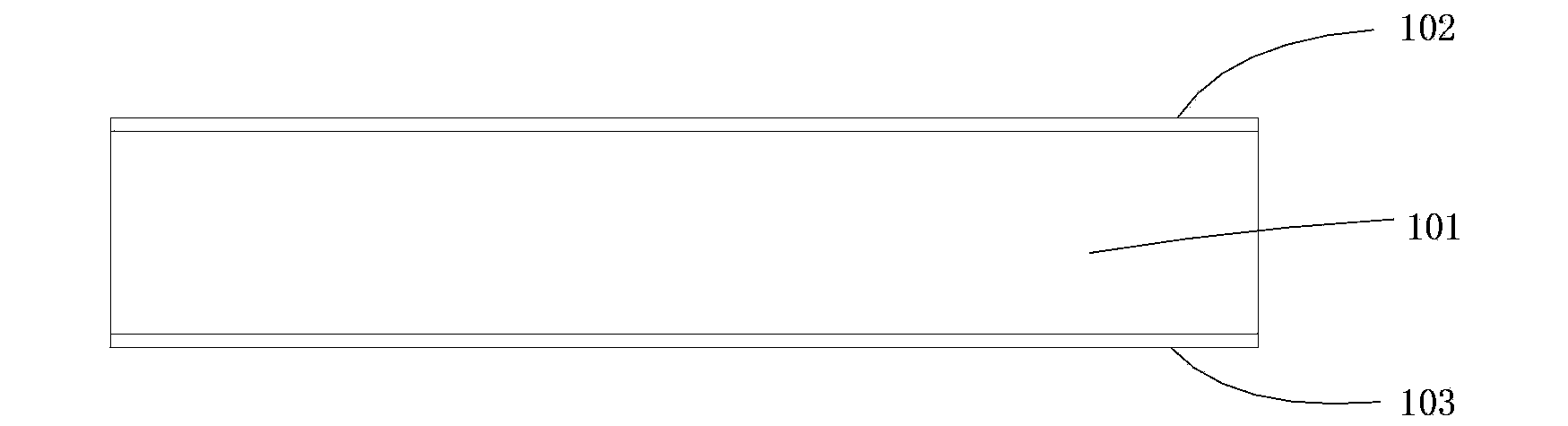
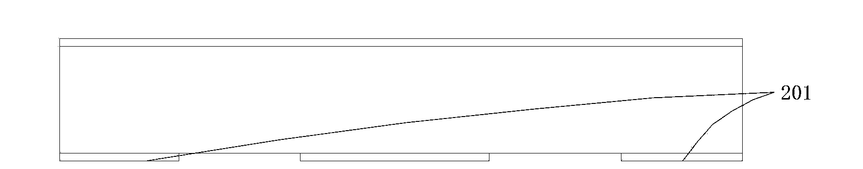
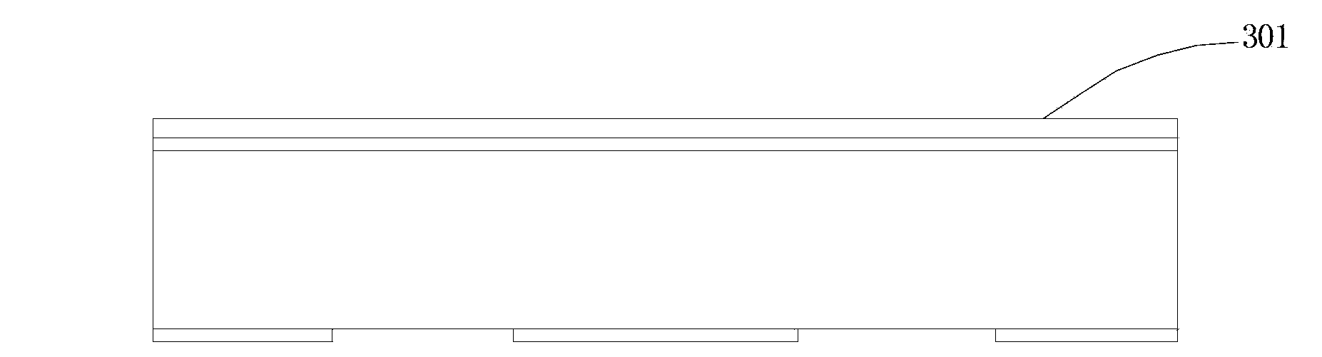
[0041] Such as Picture 11 Shown: the novel MEMS piezoelectric vibration energy collector structure of the present invention includes a substrate 101; the substrate is provided with double-sided release barrier strips 102, 103; the front barrier strip 102 has a metal conductive layer (bottom) 301; On the metal conductive layer (bottom) 301, the piezoelectric ceramic sheet 601 and the metal conductive layer (bottom) are connected by conductive glue 501. Before preparing the conductive glue layer 501, it is necessary to prepare patterned light on the metal conductive layer (bottom) 301 in advance. Resist 401; the bond and the subsequent piezoelectric ceramic sheet 601 are thinned and wet etched to a suitable thickness 701, and then the metal conductive layer (top) is deposited on the entire sheet, so that the metal layer above the piezoelectric ceramic sheet serves as the top electr...


PUM


Abstract

The invention designs a structure of a novel MEMS piezoelectric vibration energy collector and a manufacturing method of the novel MEMS piezoelectric vibration energy collector. According to the structure, the novel MEMS piezoelectric vibration energy collector comprises a dually-polished substrate and double substrate protecting layers. According to the manufacturing method of the novel MEMS piezoelectric vibration energy collector, a front metal conductive layer (the bottom) is used as an output bottom electrode; a patterned conductive adhesive is manufactured on an upper metal layer; a PZT piezoelectric patch is bonded to a silicon wafer bottom electrode through the conductive adhesive; full-piece covering of a top electrode metal conductive layer (the top) is conducted; KOH is corroded through a window in the back-side substrate protecting layer, and a cantilever beam structure which mainly contains epoxy resin and does not contain Si is released; a cantilever beam-quality block structure is released through scribing. The novel MEMS piezoelectric vibration energy collector is simple in structure, easy to obtain, capable of facilitating batch production, high in sensitiveness, output level and power, wide in application range, safe and reliable.

Description

technical field [0001] The invention relates to a miniature piezoelectric vibration energy collector and a manufacturing method thereof, in particular to a miniature piezoelectric vibration energy collector based on an epoxy resin cantilever beam and a manufacturing method thereof. Background technique [0002] Micro-power supply is usually a part of passive wireless sensor network or micro-actuator. This kind of micro-sensor micro-actuator has a wide range of applications and a large demand. It requires small size and strong stability under the condition of ensuring performance. It often needs to work in Extreme, harsh environments or environments where batteries cannot be replaced at will, so micro-sensors and micro-actuators equipped with micro-power modules become quite necessary. [0003] Micro-power modules, that is, energy harvesters, are divided into piezoelectric, electromagnetic, variable capacitance and composite types. Piezoelectric has received special attentio...

Claims


Application Information

Patent Timeline
IPC IPC(8): H01L41/113H01L41/22B81B3/00B81C1/00
Inventor 吴航欧毅郑陶雷欧文刘宇
Owner INST OF MICROELECTRONICS CHINESE ACAD OF SCI
Why Eureka
Try Eureka