Battery pack unit battery voltage detection circuit

A technology of voltage detection circuit and single battery, applied in the direction of measuring current/voltage, measuring device, measuring electrical variable, etc., can solve the problems of increasing capacitance, increasing chip cost, deviation of test results, etc., and reducing the number of resistors , Reduce the chip area, the effect of small detection error

Active Publication Date: 2014-06-11
中科芯时代科技有限公司
View PDF3 Cites 12 Cited by
  • Summary
  • Abstract
  • Description
  • Claims
  • Application Information

AI Technical Summary

Problems solved by technology

This method is easily affected by the parasitic capacitance of the switch tube and the deviation of the detection result occurs. The solution is to increase the capacitance so that the parasitic capacitance can be ignored, but increasing the capacitance will occupy too much area and increase the cost of the chip

Method used


Image

  • Battery pack unit battery voltage detection circuit
  • Battery pack unit battery voltage detection circuit
  • Battery pack unit battery voltage detection circuit

Examples


Embodiment Construction

[0029] Embodiments of the present invention are described in detail below, examples of which are shown in the drawings, wherein the same or similar reference numerals denote the same or similar elements or elements having the same or similar functions throughout. The embodiments described by referring to the figures are exemplary only for explaining the present invention and should not be construed as limiting the present invention.

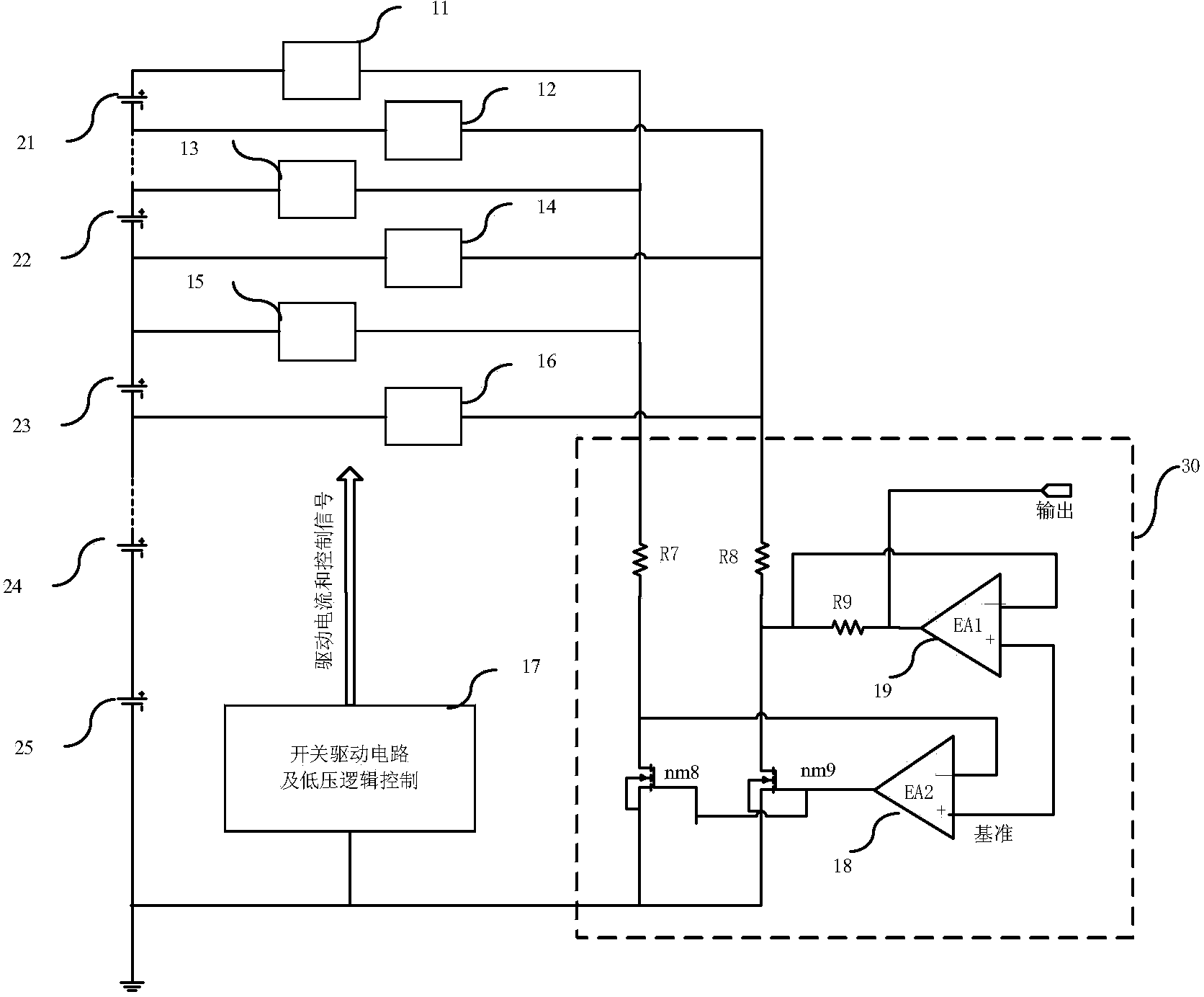
[0030] image 3 It is a schematic diagram of a single battery voltage detection circuit according to an embodiment of the present invention, which includes a plurality of series-connected batteries 21-25, a plurality of high-voltage switches 11-16, a switch driving circuit, a low-voltage logic controller 17, and a high common-mode error amplifier circuit 30. A plurality of high-voltage switches 11-16 are respectively connected to each electrode of the battery 21-25, and the high-voltage switches 11-16 are turned on or off under the control of th...


PUM


Abstract

The invention discloses a battery pack unit battery voltage detection circuit which comprises a high-voltage analogue switch array. The input end of the high-voltage analogue switch array is connected with the two ends of a unit battery to be detected, and the output end of the high-voltage analogue switch array is connected with a high-common-mode input error amplifier. The high-common-mode input error amplifier is used for converting a high-common-mode battery signal into a differential signal with the low voltage as a reference voltage to perform detection. When the voltage of the unit battery to be detected in the battery pack is detected, a corresponding set of high-voltage switches connected to battery positive and negative plate in the high-voltage analogue switch array are switched on, and a battery voltage signal is directly output to the high-common-mode input error amplifier. When the voltage of the unit battery to be detected in the battery pack is detected, the high-voltage switches connected to the battery positive and negative plate are switched on, and the battery voltage signal is output to the high-common-mode input error amplifier. Compared with a traditional detection circuit, the high-voltage detection circuit saves chip area and meanwhile improves the detection precision.

Description

technical field [0001] The invention relates to the field of high-voltage analog integrated circuit design, in particular to a voltage detection circuit of a single cell of a battery pack. Background technique [0002] The power battery pack is the basic part of maintaining the power of the car. In order to prolong the service life of the battery, detect and eliminate battery faults in time, and charge and discharge it reasonably, a battery pack management system is essential. [0003] Taking polymer lithium-ion batteries as an example, it has high energy density, high output power, high charging efficiency, long service life, and no pollution. It is an important energy storage component for new energy vehicles. Its shortcoming is that it needs a special protection circuit to prevent overcharging and overdischarging, or the service life problems caused by the unbalanced power of the single cells in the battery pack. Accurate detection of battery cell voltage is the premise ...

Claims


Application Information

Patent Timeline
Patent Type & Authority Applications(China)
IPC IPC(8): G01R19/00
Inventor 付佳赵野郝炳贤
Owner 中科芯时代科技有限公司
Why Eureka
Try Eureka