Implantation type detection device on the basis of fluorescence detection method
A fluorescence detection and detection device technology, applied in diagnostic recording/measurement, medical science, sensors, etc., can solve the problems of limited electrochemical selectivity, limited sensor life, reading failure, etc., and achieve good durability, high sensitivity, and long life. long effect
- Summary
- Abstract
- Description
- Claims
- Application Information
AI Technical Summary
Problems solved by technology
Method used
Image

Examples
Embodiment Construction
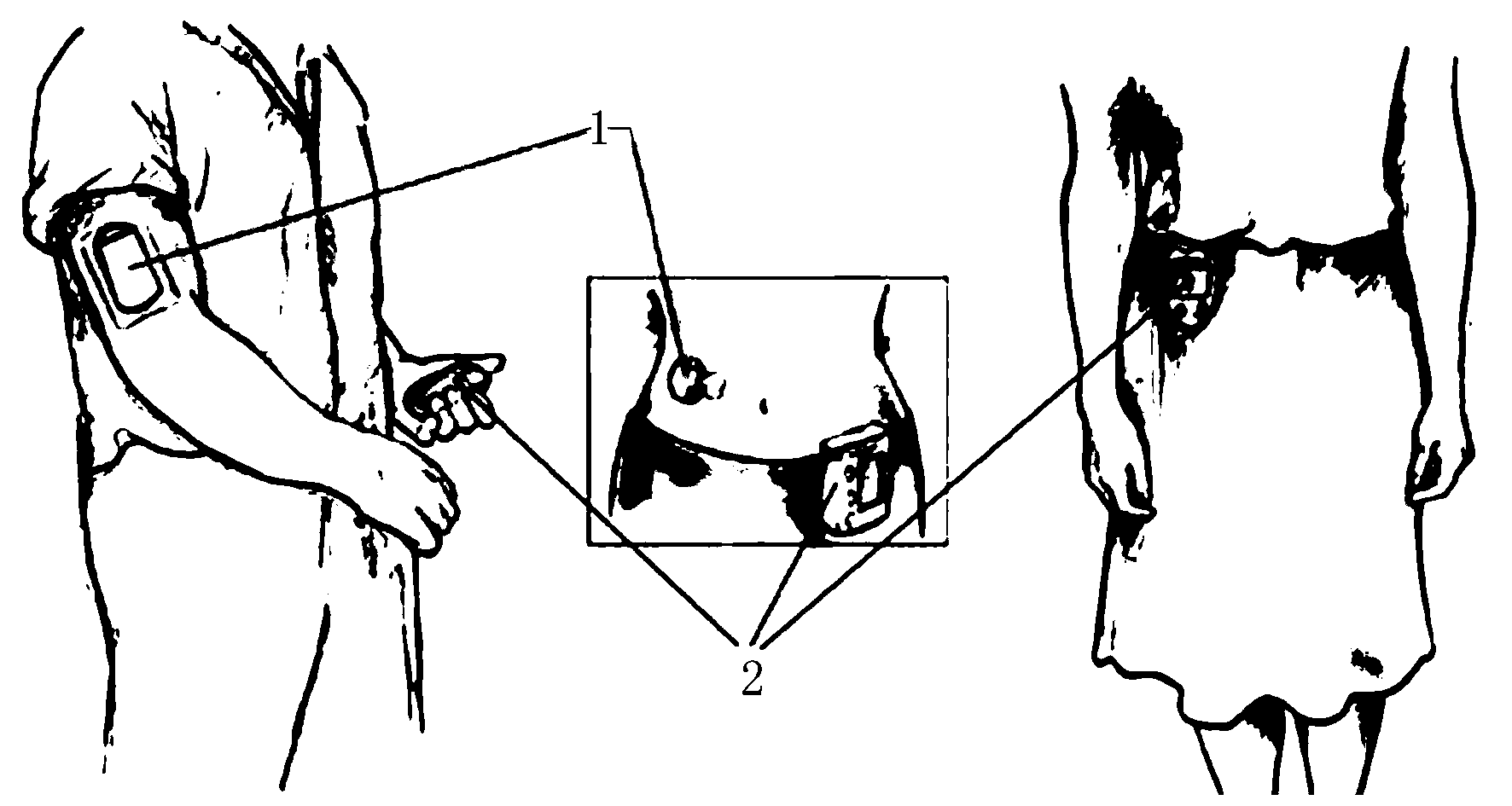
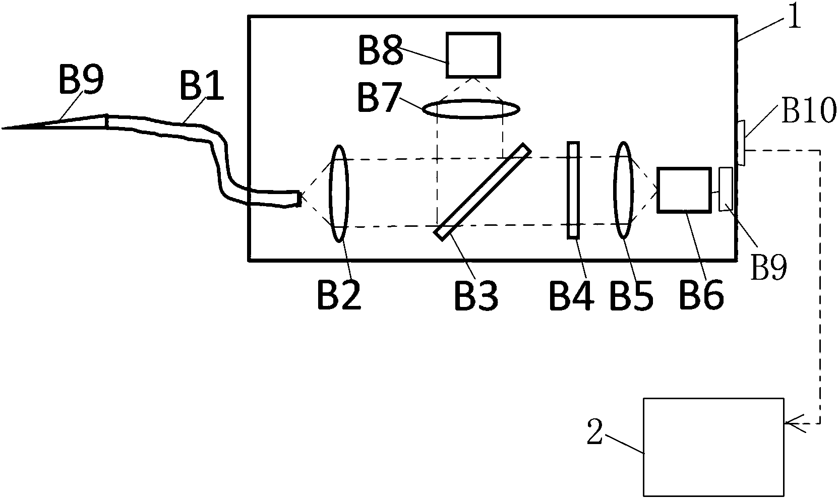
[0023] Refer to attached Figure 1~3 , the implantable detection device based on the fluorescence detection method includes a sensor head B9, a signal generator / measurer 1 and a signal receiver / detector 2; the sensor head B9 is implanted in the body, exposed to subcutaneous tissue fluid, and senses the The concentration of molecules; the sensor head B9 is connected to the signal generation / measurement device 1 through the optical fiber B1, and the signal generation / measurement device 1 and the signal receiver / detector 2 perform data transmission through wired or wireless methods; the signal generation / measurement device 1 generates The excitation light and the signal fluorescence are transmitted through the same optical fiber, and the signal receiving / detector 2 receives and detects the light intensity of the signal fluorescence, so as to obtain the quantitative concentration of a certain compound.
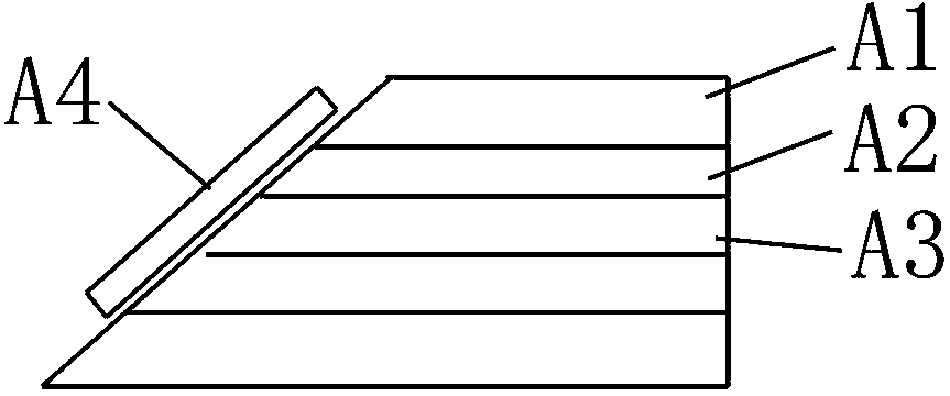
[0024] The sensing head B9 is transformed from an optical fiber, and the dete...
PUM
 Abstract
Description
Claims
Application Information
 - R&D
- Intellectual Property
- Life Sciences
- Materials
- Tech Scout
- Unparalleled Data Quality
- Higher Quality Content
- 60% Fewer Hallucinations
Browse by: Latest US Patents, China's latest patents, Technical Efficacy Thesaurus, Application Domain, Technology Topic, Popular Technical Reports.
© 2025 PatSnap. All rights reserved.Legal|Privacy policy|Modern Slavery Act Transparency Statement|Sitemap|About US| Contact US: help@patsnap.com