Cloud particle spectrum distribution measuring method and system

A measurement system, cloud particle technology, applied in the direction of measurement device, particle size analysis, scattering characteristic measurement, etc., can solve the problems of low measurement accuracy of cloud particles, no cloud particles, etc.

Active Publication Date: 2014-06-18
TIANJIN UNIV
View PDF9 Cites 36 Cited by
  • Summary
  • Abstract
  • Description
  • Claims
  • Application Information

AI Technical Summary

Problems solved by technology

Patent CN102175591A utilizes the Mie forward scattering signal of cloud particles to the laser, divides the signal into two channels, and performs particle size measurement and particle determination in the depth of field respectively, and uses the scattered light intensity inf...

Method used


Image

  • Cloud particle spectrum distribution measuring method and system
  • Cloud particle spectrum distribution measuring method and system
  • Cloud particle spectrum distribution measuring method and system

Examples


Embodiment 1

[0028] Embodiment 1: Cloud Particle Spectrum Distribution Measurement System

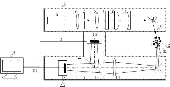
[0029] Such as figure 1 As shown, the present invention firstly provides a cloud particle spectrum distribution measurement system, which system includes a sheet polarized laser beam generation system, a particle scattered light detection system and a computer system;

[0030] The sheet polarized laser beam generation system includes a sheet polarized laser beam generation box 1, a laser 5 is arranged in the box, and a beam expander lens 6, a pinhole filter 7, and a collimator lens are sequentially arranged along the optical path of the laser output light. 8. Polarizer 9, convex cylindrical lens 10, concave cylindrical lens 11 and first reflector 12. An exit window 19 is provided on the box on the reflected light path of the first reflector, and the reflected light passes through the exit window. Incident to cloud particle scattering detection area 2;

[0031] The particle scattered light detec...

Embodiment 2

[0033] Embodiment 2: Cloud Particle Spectrum Distribution Measurement Method

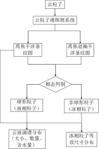
[0034] Such as image 3 As shown, the method for measuring cloud particle spectrum distribution provided by the invention, the specific steps are as follows:

[0035] 1. The laser beam emitted by the laser in the box of the sheet polarized laser beam generation system is collimated into a plane wave through a beam expander lens, a pinhole filter and a collimator lens, and then forms a linearly polarized light through a polarizer, and then passes through a convex The cylindrical lens and the concave cylindrical lens compress the light beam into a sheet-like light beam, and then enter the cloud particle scattering detection area from the exit window of the box through the first reflector;

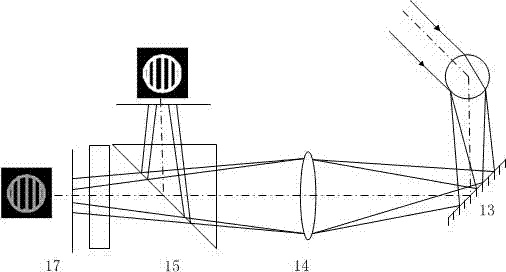
[0036] 2. Cloud particle scattered light enters the particle scattered light detection system from the incident window on the particle scattered light detection box, and then the cloud particle scattered light e...


PUM


Abstract

The invention discloses a cloud particle spectrum distribution measuring method and system. The measuring system comprises a disc-shaped polarization laser beam generating system, a grain scattered light detection system and a computer system. The measuring method provided by the invention comprises the steps of irradiating cloud grains by polarized light, dividing scattered signals into two ways by a beam splitter prism, carrying out detection of an out-of-focus interference pattern on one way of scattered signals directly by a photoelectric image detector while carrying out detection on a depolarization out-of-focus interference pattern on the other way of scattered signals by a depolarizer and a photoelectric image detector, distinguishing a cloud particle phase state by comparing the out-of-focus interference pattern with the depolarization out-of-focus interference pattern, and inverting according to out-of-focus interference fringe pattern information to obtain a liquid phase cloud particle size and an ice phase cloud particle equivalent size. The cloud particle distribution measuring method provided by the invention serves as a new diagnostic method for atmosphere particle detection, can be used for onboard cloud micro physic detection, and is capable of implementing on-line measurement of the phase state, size, distribution and water content of cloud particles so as to provide the powerful basis for meteorology forecast and manual intervention.

Description

technical field [0001] The invention belongs to the technical field of cloud particle spectrum analysis and detection, and in particular relates to a cloud particle spectrum distribution measurement method and a measurement system for measuring the cloud particle spectrum distribution in the atmosphere and discriminating the cloud particle phase state. Background technique [0002] Cloud microphysical characteristics are usually described by cloud particle spectral distribution (phase state, scale, concentration and water content, etc.). The detection of cloud particle spectrum distribution is an important issue in the research fields of cloud physics, atmospheric physics and atmospheric dynamics, which can provide a theoretical basis for the prediction of artificial weather modification and small and medium-scale disaster weather. [0003] A variety of measurement techniques and methods based on different measurement principles and suitable for different measurement ranges ...

Claims


Application Information

Patent Timeline
IPC IPC(8): G01N15/02G01N15/06G01N21/49
Inventor 张红霞翟梦冉吕且妮刘京贾大功
Owner TIANJIN UNIV
Why Eureka
Try Eureka