Offshore drilling controllable buoyant block

A technology for marine drilling and buoyancy blocks, applied in drilling equipment, drill pipes, drill pipes, etc., can solve the problems of vortex-induced vibration of buoyancy blocks, riser failure, riser wear, etc., to reduce current excitation and eddy current vibration, The effect of improving work efficiency and reducing workload

Inactive Publication Date: 2014-06-25
SOUTHWEST PETROLEUM UNIV
View PDF4 Cites 11 Cited by
  • Summary
  • Abstract
  • Description
  • Claims
  • Application Information

AI Technical Summary

Problems solved by technology

At present, the buoyancy blocks mainly used in engineering are foam plastics and air tank buoyancy blocks. These two buoyancy blocks have great deficiencies. First, the buoyancy blocks are in relatively deep water depths and are subject to high hydrostatic pressure. , it is easy to be infiltrated by water and lose the buoyancy effect. When the buoyancy block fails, the riser will be unstable, the deformation of the riser, the axial load, and the rotation angle of the spherical joint will all increase. Once the drilling limit window is exceeded, drilling will be forced stop
Secondly, due to the long-term action of currents and waves in the ocean, the buoyancy block will produce vortex-induced vibration, which will eventually cause fatigue damage to the buoyancy block
[0003] Documents such as SPE96290, IADC / SPE112648, SPE74534, IADC / SPE39295 and other articles and field data confirm that excessive drag force, excessive offset and excessive riser ball joint rotation angle will cause drilling operation to stop; The accumulation of vibration fatigue damage induced by eddy currents behind the water pipe will lead to premature failure of the riser, such as riser wear, shedding, fracture and collapse, etc.
Therefore, it is difficult for traditional buoyancy blocks to achieve the functions of providing variable buoyancy for risers, reducing wave loads and reducing eddy-induced vibrations

Method used


Image

  • Offshore drilling controllable buoyant block
  • Offshore drilling controllable buoyant block
  • Offshore drilling controllable buoyant block

Examples


Embodiment Construction

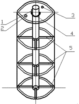
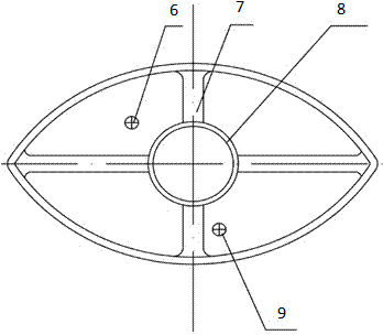
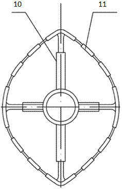
[0011] The details and work flow of the controllable buoyancy block for ocean drilling proposed by the present invention will be described in detail below in conjunction with the accompanying drawings.

[0012] In severe sea conditions, the control software controls the air compressor to inject air into the buoyancy block through the intake valve of the controllable buoyancy block of offshore drilling, and the outer material of the buoyancy block can expand after gas injection to provide variable buoyancy for the riser . After the sea state recovers, the control software sends instructions to the exhaust valve of the buoyancy block through the same path to discharge the rated gas volume, and the buoyancy block shrinks to return to the original equilibrium state. The buoyancy block has just played the effect of providing variable buoyancy like this. In addition, the guide ring on the top of the buoyancy block cooperates with the air injection of the compressor to automatically...


PUM


Abstract

The invention discloses an offshore drilling controllable buoyant block with a guide ring, and belongs to buoyant blocks special for ocean deepwater drilling engineering. The offshore drilling controllable buoyant block is suitable for the complex environment of on-sea oil and gas exploitation. According to the offshore drilling controllable buoyant block, energy input to a marine riser by water flow can be reduced, water flow stirring and eddy vibration can be reduced, ocean current and sea wave impact loads borne by the marine riser are minimum, and variable buoyancy can be further provided for the marine riser. The offshore drilling controllable buoyant block is composed of a deflection spring, an air inlet valve, an air outlet valve, the guiding ring, stretchable supporting rings and an outer cavity, and the core parts of the offshore drilling controllable buoyant block are the stretchable supporting rings composed of stretchable chains and stretchable arms. The state of the offshore drilling controllable buoyant block can be adjusted by the guiding ring at the top according to the water flow direction to enable the water passing face and the water facing face of the offshore drilling controllable buoyant block to be minimum. In addition, when the offshore drilling controllable buoyant block suffers severe sea conditions, control software used in a mated mode computes real-time loads borne by the marine riser and the offshore drilling controllable buoyant block and sends a command to a compressor after data are processed, a proper amount of air is inflated into or discharged out from the offshore drilling controllable buoyant block through the compressor, and the function of providing the variable buoyancy for the marine riser is achieved.

Description

technical field [0001] The invention is a controllable buoyancy block for ocean drilling, which belongs to the special buoyancy block for ocean deep water drilling engineering, and is suitable for the complex environment of offshore oil and gas exploration and development. Background technique [0002] More than 90% of the world's undiscovered offshore oil and gas reserves are buried in formations with water depths below 1000m. Therefore, marine deepwater oil wells are the key to promoting the development of the petroleum industry, but the depth of water seriously restricts the development of marine deepwater drilling. At this stage, my country's offshore oil drilling has gradually moved towards the deep sea. For example, the 981 drilling platform with independent intellectual property rights has a drilling water depth of 3,000 meters, which provides a strong guarantee for the exploitation of my country's deep-water offshore oil and gas resources. However, as the water dept...

Claims


Application Information

Patent Timeline
Patent Type & Authority Applications(China)
IPC IPC(8): E21B17/10
Inventor 石晓兵范鹏飞黄兵苗娟
Owner SOUTHWEST PETROLEUM UNIV
Why Eureka
Try Eureka