
Optical fiber amplifier dynamic gain slope equalizer and manufacturing technology thereof

A fiber amplifier and dynamic gain technology, applied in optics, instruments, optical components, etc., can solve problems such as signal power imbalance between DWDM channels, and achieve important practical value, low cost, and high yield

Active Publication Date: 2014-06-25
QST CORP
View PDF5 Cites 21 Cited by
  • Summary
  • Abstract
  • Description
  • Claims
  • Application Information

AI Technical Summary

Problems solved by technology

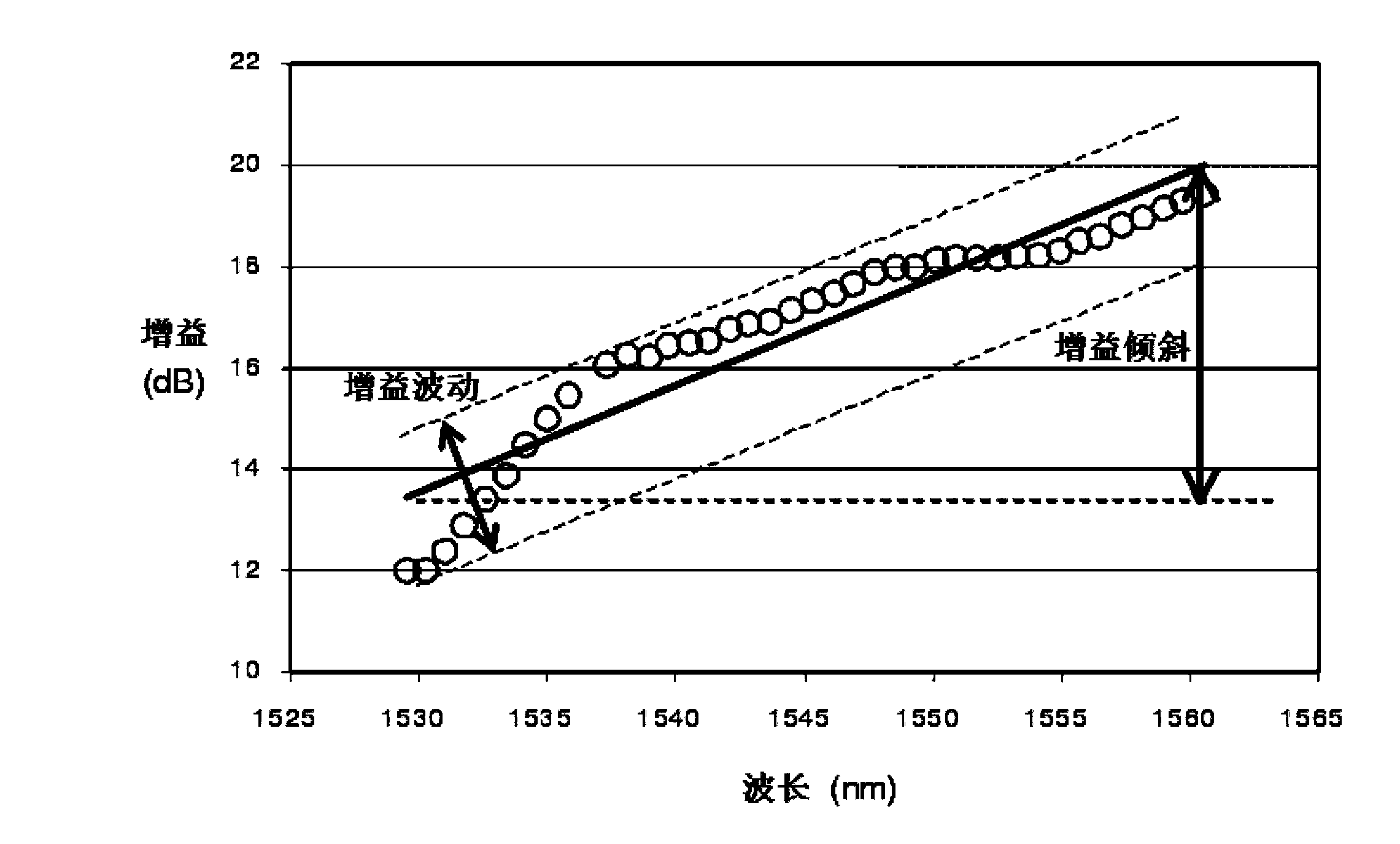
[0013] The technical problem to be solved by the present invention is to provide a dynamic gain slope equalizer for optical fiber amplifiers, which can solve the problem of EDFA dynamic gain equalization, and can also be applied to solve the signal power imbalance between DWDM channels caused by compensation for dispersion compensation modules and SRS effects.

Method used


Image

  • Optical fiber amplifier dynamic gain slope equalizer and manufacturing technology thereof
  • Optical fiber amplifier dynamic gain slope equalizer and manufacturing technology thereof
  • Optical fiber amplifier dynamic gain slope equalizer and manufacturing technology thereof

Examples


Embodiment 1

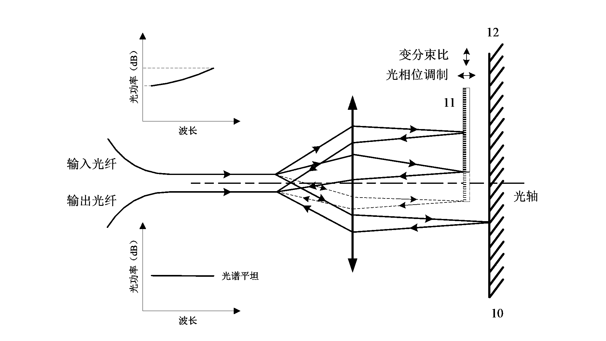
[0062] In view of the shortcomings of current DGE and DGSE device technologies such as high cost, large insertion loss, high drive power consumption, and large volume, this invention proposes a technical solution for a dynamic gain slope equalizer based on MEMS technology, using a MEMS two-degree-of-freedom micro-displacement driver, A free-space optical MZI with independent tunable optical splitting ratio and optical phase, featuring low insertion loss, large spectral slope equalization range, fast tuning, low drive power consumption, low cost, and small size, and can be directly integrated with GFF Into EDFA, thereby solves the problem of EDFA dynamic gain equalization. At the same time, it can also be applied to solve the problem of signal power imbalance between DWDM channels caused by transmission optical fiber, optical fiber dispersion compensation module, optical fiber stimulated Raman scattering (SRS) effect, etc.

[0063] see image 3, the fiber amplifier dynamic gai...

Embodiment 2

[0090]In this embodiment, both the first optical micro-mirror and the second optical micro-mirror are movable MEMS micro-mirrors.

[0091] The micro-displacement adjustment unit includes an electrostatic comb driver and an electrostatic plate driver.

[0092] The electrostatic comb driver is located on both sides of the silicon frame, and is suspended above the MEMS optical micromirror driver chip substrate by a group of silicon elastic beams, and is connected with the MEMS optical micromirror driver chip substrate; The electrostatic comb driver is used to control the micro-displacement movement of the first optical micro-mirror in the horizontal direction, so as to realize the tuning of the MZI beam splitting ratio.

[0093] In this embodiment, the electrostatic flat panel driver includes a first electrode plate and a second electrode plate; the first electrode plate is located under the first optical micro-mirror, and the second optical micro-mirror is plated on it, and the ...


PUM


Abstract

The invention discloses an optical fiber amplifier dynamic gain slope equalizer and a manufacturing technology thereof. The equalizer comprises an MEMS optical micro mirror driver chip and a double-optical fiber collimator through optical package; the MEMS optical micro mirror driver chip comprises an first optical micro reflecting mirror, a second optical micro reflecting mirror and a micro displacement regulating unit; the micro displacement regulating unit is used for controlling micro displacement motion of the first optical micro reflecting mirror and / or the second optical micro reflecting mirror in the horizontal direction or / and vertical direction, MZI splitting ratio and interference arm phase tuning can be realized, and spectral slope with inputted WDM optical signals can be dynamically controlled. The dynamic gain slope equalizer provided by the invention is manufactured by adopting the MEMS technology, has the advantages of low insertion loss, wide equalized range, small size, quick tuning speed, micro driving power and the like, can be directly integrated in the EDFA for realizing dynamic gain slope equalization, and can also be applied to the problem that signal power in the DWDM channel is not equalized due to transmission optical fiber, an optical fiber dispersion compensation module, optical fiber SRS effect and the like.

Description

technical field [0001] The invention belongs to the technical field of MEMS and optical fiber communication, and relates to a dynamic gain slope equalizer, in particular to an optical fiber amplifier dynamic gain slope equalizer; meanwhile, the invention also relates to a preparation process of the above-mentioned optical fiber amplifier dynamic gain slope equalizer. Background technique [0002] The implementation of "Broadband China Strategy" and "Broadband Internet Speed-up Project" will greatly accelerate the construction of my country's broadband optical network. The traditional point-to-point optical transmission network can no longer adapt to the leapfrog growth in the number of optical access ports and access bandwidth, and the intelligent optical network based on Automatically Switched Optical Network (ASON) technology is an inevitable development trend. The intelligent optical network not only needs to solve the problems of large-capacity transmission and broadband...

Claims


Application Information

Patent Timeline
Patent Type & Authority Applications(China)
IPC IPC(8): G02B26/08H04B10/291
Inventor 不公告发明人
Owner QST CORP
Learn More