Laminated high-gain circular polarization micro-strip array antenna based on LTCC

A microstrip array, circular polarization technology, applied in the direction of antenna, antenna array, radiating element structure, etc., can solve the development needs of the unfavorable microstrip patch antenna and the miniaturization of the carrier conformal design, and cannot take into account the circular polarization. and gain characteristics, reducing the mechanical strength of the antenna, etc., to avoid the output mismatch in the input domain, reduce the phase and amplitude errors, and improve the stability and reliability.

Inactive Publication Date: 2014-06-25
UNIV OF ELECTRONICS SCI & TECH OF CHINA
View PDF5 Cites 22 Cited by
  • Summary
  • Abstract
  • Description
  • Claims
  • Application Information

AI Technical Summary

Problems solved by technology

However, these methods are all at the expense of increasing the thickness or area of ​​the antenna, which is not conducive to the conformal design of the microstrip patch antenna and the carrier and the development requirements of miniaturization, making the antenna structure complex or unable to achieve circular polarization. The existence of the antenna also reduces the mechanical strength of the antenna itself, and it is often impossible to take into account the circular polarization and gain characteristics of the circularly polarized array antenna

Method used


Image

  • Laminated high-gain circular polarization micro-strip array antenna based on LTCC
  • Laminated high-gain circular polarization micro-strip array antenna based on LTCC
  • Laminated high-gain circular polarization micro-strip array antenna based on LTCC

Examples


Embodiment Construction

[0024] The present invention will be further described in detail below with reference to the accompanying drawings and specific examples, but the embodiments of the present invention are not limited thereto.

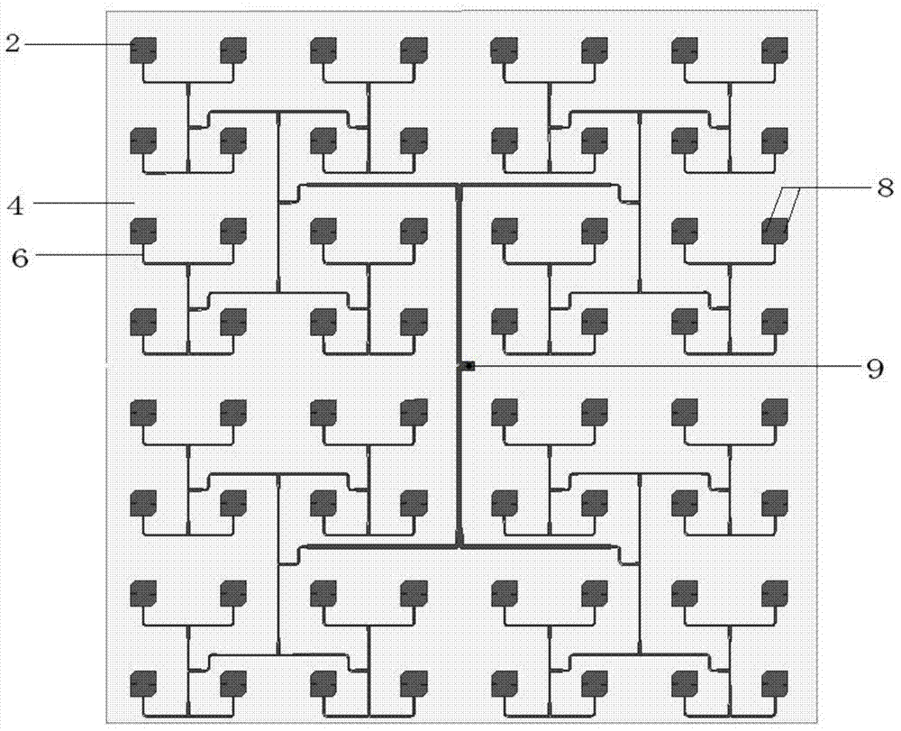
[0025] Such as Figure 6 , Figure 7 As shown, the center frequency point of the microstrip patch antenna provided by the embodiment of the present invention is 10.3 GHz, which is a common antenna for transmitting and receiving of the microstrip patch. The present invention can realize a microstrip patch antenna with an impedance bandwidth exceeding 560 MHz, and the antenna gain can reach 22.10dBi, and the axial ratio of the antenna can reach 1.77dB.

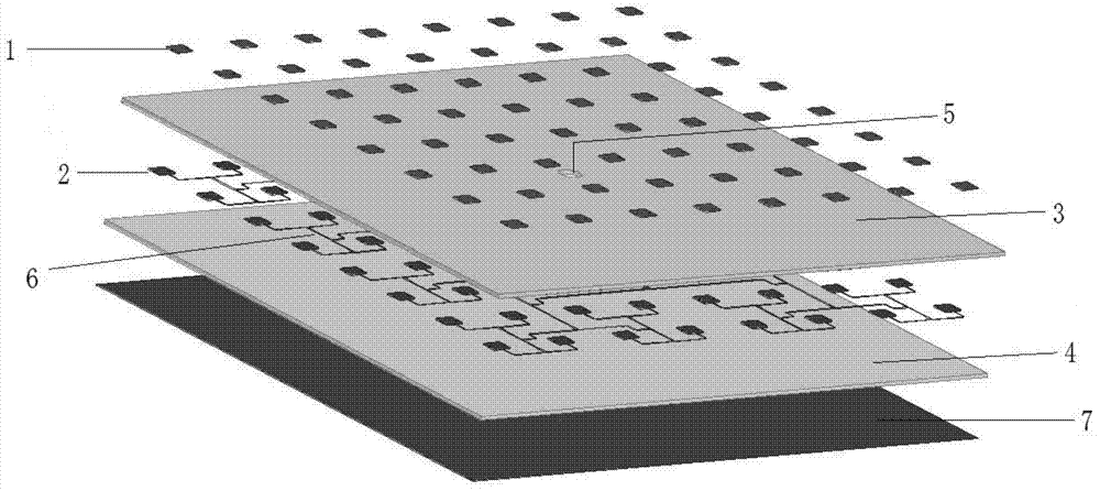
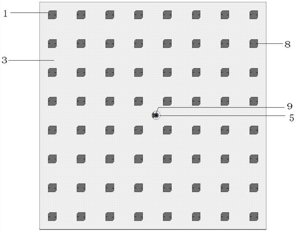
[0026] A LTCC stacked circularly polarized microstrip array antenna provided in this embodiment has a structure such as Figure 1 to Figure 5 shown, including:

[0027] Lower dielectric substrate: The substrate is made of five LTCC cast film sheets with a thickness of 0.1mm and a dielectric constant of 5.9. The lower su...


PUM


Abstract

The invention aims at overcoming the defects of an existing micro-strip patch antenna in the aspects of the high gain, the wide band and the circular polarization and providing a laminated circular polarization micro-strip patch antenna based on the LTCC technology. The antenna comprises an upper radiation metal patch antenna array layer, a lower radiation metal patch antenna array layer, an upper dielectric substrate layer, a lower dielectric substrate layer, a feed network, a grounding metal layer and a coaxial connector probe. The antenna is characterized in that the upper radiation metal patch antenna array layer and the lower radiation metal patch antenna array layer are the same in shape and size, each antenna array is composed of four small antenna arrays, each small antenna array is composed of four sub-arrays, each sub-array is composed of four radiation metal patches, each radiation metal patch is a square with a chamfer, and a set of opposite sides of each radiation metal patch are provided with rectangular gaps. The antenna can better meet the requirements for performance of the high gain, the wide band and the circular polarization of the micro-strip patch antenna, and the structure is simple.

Description

technical field [0001] The invention belongs to the technical field of antennas, in particular to an LTCC laminated high-gain circularly polarized microstrip array antenna. Background technique [0002] Microstrip patch antennas have the advantages of small size, light weight, thin profile and easy to conform to the carrier. In recent years, they have been widely used in radar, missile measurement and control, weapon fuze, electronic countermeasures, mobile communication, remote sensing and telemetry and other fields. In airborne or missile-borne applications, the performance requirements of microstrip patch antennas are particularly emphasized for their high gain, wide frequency band and circular polarization. However, the frequency band of the microstrip patch antenna is very narrow. The current common methods include increasing the thickness of the substrate, reducing the dielectric constant of the substrate, adopting a multi-layer structure, and adding impedance matching...

Claims


Application Information

Patent Timeline
Patent Type & Authority Applications(China)
IPC IPC(8): H01Q21/00H01Q1/38H01Q1/36
Inventor 张怀武郝欣欣段耀铎
Owner UNIV OF ELECTRONICS SCI & TECH OF CHINA
Why Eureka
Try Eureka