On-board electronic cabinet

A chassis and electronic technology, applied in the direction of electrical equipment casing/cabinets/drawers, electrical components, magnetic field/electric field shielding, etc., can solve the problem of non-metallic materials being prone to aging and failure, affecting equipment performance and service life, and metal materials damage and corrosion, etc. problems, to achieve the effect of improving the reliability and applicability of work, improving the performance of electromagnetic interference resistance, and improving the performance of high temperature resistance

Inactive Publication Date: 2014-06-25
AVIC HUADONG OPTOELECTRONICS (SHANGHAI) CO LTD
View PDF4 Cites 16 Cited by
  • Summary
  • Abstract
  • Description
  • Claims
  • Application Information

AI Technical Summary

Problems solved by technology

In recent years, with the use of large-scale integrated circuits, the structural design of electronic equipment has developed towards the direction of ultra-small assembly, and the requirements for electronic system heat meters have become higher and higher, especially for electronic products used in special working environments. , such as electronic equipment that has been exposed to harsh marine climate conditions (temperature, high humidity, salt spray) for a long time, the metal materials in the equipment are easily damaged and corroded, and the non-metallic materials are also easily aged and invalidated, resulting in poor performance of components. Decrease, or even cause electrical short circuit, which seriously affects the performance and service life of the equipment. At the same time, due to the continuous improvement of electromagnetic compatibility design requirements, there is an urgent need for a versatile equipment that can work independently and be isolated from the outside world. The heat dissipation design has become a A crucial step for such devices to function properly

Method used


Image

  • On-board electronic cabinet
  • On-board electronic cabinet
  • On-board electronic cabinet

Examples


Embodiment Construction

[0021] Below with reference to the accompanying drawings, through the description of the embodiments, the specific embodiments of the present invention, such as the shape, structure, mutual position and connection relationship between the various parts, the role and working principle of the various parts, etc., will be further described. Detailed instructions:

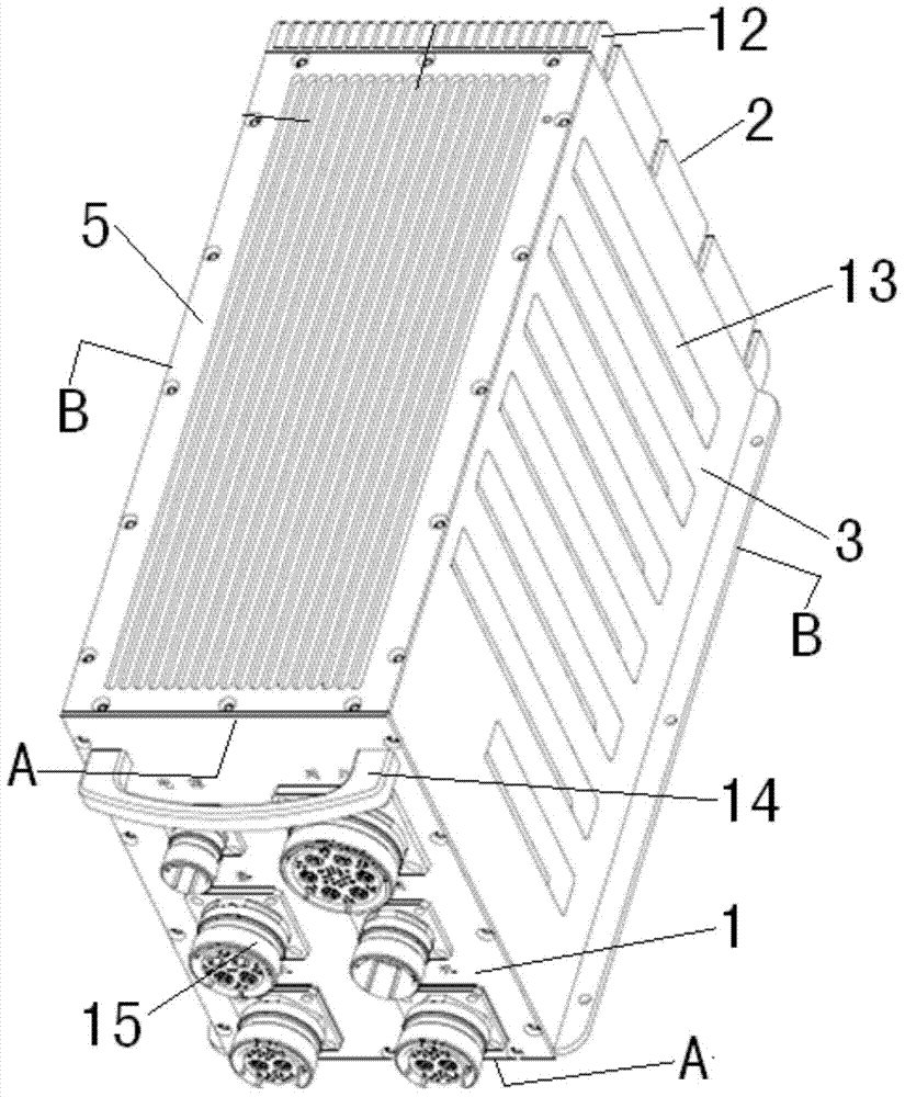
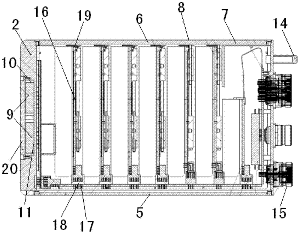
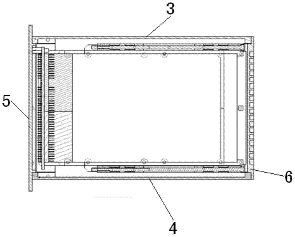
[0022] as attached figure 1 — attached image 3 As shown, the present invention is an airborne electronic cabinet, comprising a front panel 1, a rear cover 2, an upper cover 3, a bottom plate 4, a left side panel 5, a right side panel 6, the front panel 1, the rear cover Plate 2, upper cover plate 3, bottom plate 4, left side plate 5, and right side plate 6 form a hollow square frame structure, the front panel 1, rear cover plate 2, upper cover plate 3, bottom plate 4, left side Plate 5, the inner surface of the right side plate 6 is provided with an oxide layer 7 formed by conductive oxidation treatment, the front p...


PUM


Abstract

The invention provides an on-board electronic cabinet applied to the technical field of aviation electronic products. A front panel (1), a rear cover plate (2), an upper cover plate (3), a base plate (4), a left side plate (5) and a right side plate (6) of the on-board electronic cabinet form a hollow square frame structure. The inner surfaces of the front panel (1), the rear cover plate (2), the upper cover plate (3), the base plate (4), the left side plate (5) and the right side plate (6) are respectively provided with an oxidation layer (7) which is formed through conductive oxidation treatment. The outer surfaces of the front panel (1), the rear cover plate (2), the upper cover plate (3), the base plate (4), the left side plate (5) and the right side plate (6) are respectively coated with an enamel paint layer (8). According to the on-board electronic cabinet, the structure is simple, the electromagnetic compatibility is guaranteed, the resistance to electromagnetic interference is improved, the heat dissipation effect is improved, it is guaranteed that the on-board electronic cabinet can be operated under severe flight conditions, and work reliability and the adaptability of the on-board electronic cabinet and an airplane where the on-board electronic cabinet is carried are improved.

Description

technical field [0001] The invention belongs to the technical field of avionics products, and more specifically relates to an airborne electronic case. Background technique [0002] With the rapid development of avionics technology, the level of the airborne electronic chassis has become one of the important symbols to measure the performance of the aircraft. Looking back at the development process of airborne electronics, many special electronic chassis suitable for different models have been developed successively, such as: integrated avionics systems for fire control and flight control, multi-functional radar systems, atmospheric data processing systems, and weapon external storage management systems , integrated display system, data transmission system and other different types of tasks. The performance of the airborne electronic chassis hardware is determined by two parts: circuit characteristics and structural characteristics. The circuit characteristics determine the...

Claims


Application Information

Patent Timeline
Patent Type & Authority Applications(China)
IPC IPC(8): H05K5/00H05K7/20H05K9/00
Inventor 熊小辉杨新军蔡庆楠巫越陈国胜徐淑波
Owner AVIC HUADONG OPTOELECTRONICS (SHANGHAI) CO LTD
Why Eureka
Try Eureka