
Automatic positioning paper feeding mechanism

An automatic positioning and paper feeding technology, applied in the direction of object supply, object separation, pile separation, etc., can solve the problems of rising demand for creasing die-cutting machines, inability to take care of corrugated cardboard, complex structure, etc., to achieve increased left and right positioning functions, The effect of simple structure and reduced volume

Inactive Publication Date: 2014-07-02
张香宏
View PDF4 Cites 2 Cited by
  • Summary
  • Abstract
  • Description
  • Claims
  • Application Information

AI Technical Summary

Problems solved by technology

[0002] With the continuous improvement of national living standards and the rapid development of social productivity, the packaging requirements for various products are also constantly improving. Therefore, cardboard boxes, cardboard boxes, trademarks, various leather and plastic products for decoration, etc. Indentation die-cutting is required, and the demand for indentation die-cutting machines is rising rapidly. At present, semi-automatic flat-indentation die-cutting machines are commonly used in the market, which require manual paper feeding, and a small number of packaging users choose automatic Flat-bed die-cutting machine, due to the increase in labor costs year by year, automatic flat-bed die-cutting machine is more and more popular, but the automatic paper feeding mechanism of the automatic die-cutting machine produced at home and abroad is complex in structure, The price is high and the function is single. The bridge runway and the left and right positioning mechanisms must be installed between the automatic paper feeding department and the die-cutting department, and it cannot take care of thinner cardboard and thicker corrugated cardboard.

Method used


Image

  • Automatic positioning paper feeding mechanism

Examples


Embodiment Construction

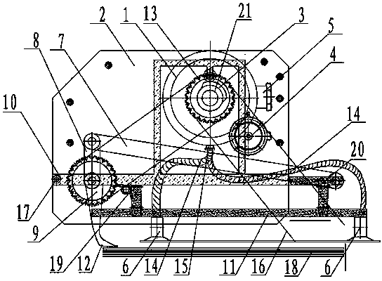
[0015] Such as figure 1 As shown, the automatic positioning paper feeding mechanism includes suction distribution valve 1, frame 2, guide rail lifting cam 3, left and right positioning motor 4, vacuum pump connection seat 5, paper suction nozzle 6, connecting rod 7, crank 8, crank sprocket 9. Guide rail 10 of paper-absorbing nozzle frame, paper-absorbing nozzle frame 11, paper presser foot 12, main sprocket 13, suction pipe 14, main drive chain 16 and main sprocket shaft 21, and main sprocket shaft 21 is rotatably installed on the frame 2, the suction distribution valve 1, the guide rail lifting cam 3 and the main sprocket 13 are respectively installed on the main sprocket shaft 21, the left and right positioning motors 4 are installed on the frame 2, and the vacuum pump connection seat 5 is installed on the suction distribution valve 1 , the paper-absorbing frame 11 is two layers up and down, movably connected by pivot pin 20, the paper-absorbing nozzle 6 is fixedly connected...


PUM


Abstract

The invention discloses an automatic positioning paper feeding mechanism which comprises an air suction distribution valve (1), a machine frame (2), a guide rail lifting cam (3), a horizontal positioning motor (4), a vacuum pump connecting base (5), a paper suction nozzle (6), a connecting rod (7), a crank (8), a crank chain wheel (9), a paper suction nozzle frame guide rail (10), a paper suction nozzle frame (11), a paper pressing foot (12), a main chain wheel (13), an air suction pipe (14), a main driving chain (16) and a main chain wheel shaft (21). According to the automatic positioning paper feeding mechanism, a gap bridge track between an existing automatic paper feeding mechanism and a die-cutting machine is omitted, pre-localization and horizontal positioning functions are added, more than fifty percent of production cost of the automatic paper feeding mechanism is reduced, more than half of the size is reduced, performance is doubled, and the automatic positioning paper feeding mechanism has the advantages of being simple in structure, easy to assemble and debug, wide in paperboard application range, capable of achieving automatic positioning and paper feeding for paperboards and corrugated boards and capable of reducing labor cost to a great extent.

Description

technical field [0001] The invention relates to the field of printing and packaging machinery, in particular to an automatic positioning paper feeding mechanism. Background technique [0002] With the continuous improvement of national living standards and the rapid development of social productivity, the packaging requirements for various products are also constantly improving. Therefore, cardboard boxes, cardboard boxes, trademarks, various leather and plastic products for decoration, etc. Indentation die-cutting is required, and the demand for indentation die-cutting machines is rising rapidly. At present, semi-automatic flat-indentation die-cutting machines are commonly used in the market, which require manual paper feeding, and a small number of packaging users choose automatic Flat-bed die-cutting machine, due to the increase in labor costs year by year, automatic flat-bed die-cutting machine is more and more popular, but the automatic paper feeding mechanism of the au...

Claims


Application Information

Patent Timeline
Patent Type & Authority Applications(China)
IPC IPC(8): B65H3/08B65H3/46B65H5/22
Inventor 张香宏
Owner 张香宏
Learn More