Dual dsp redundant inertial platform controller
An inertial platform and controller technology, applied in general control systems, control/adjustment systems, instruments, etc., can solve problems such as failure to operate, lack of backup controllers for processors, etc., to ensure safe operation, normal and stable operation, and guarantee Effects of Accuracy and Stability
- Summary
- Abstract
- Description
- Claims
- Application Information
AI Technical Summary
Problems solved by technology
Method used
Image
Examples
specific Embodiment approach 1
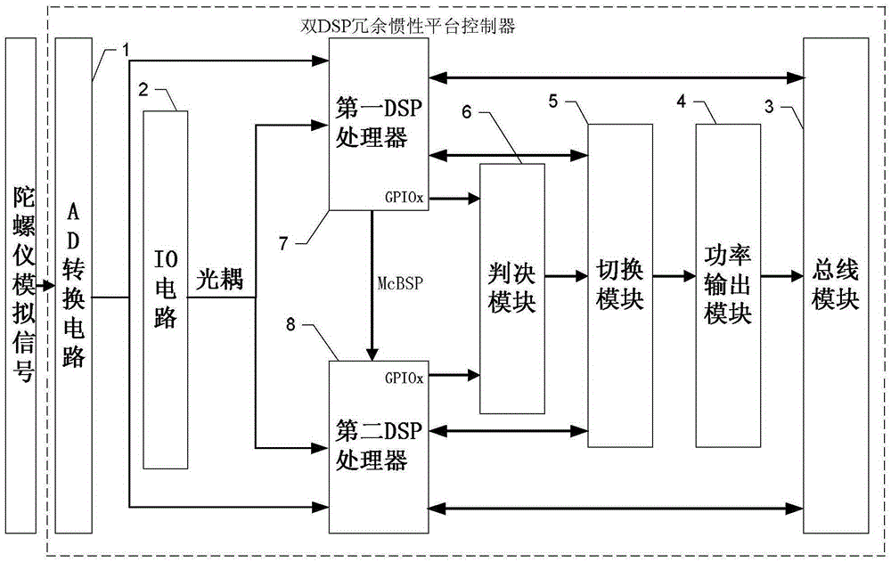
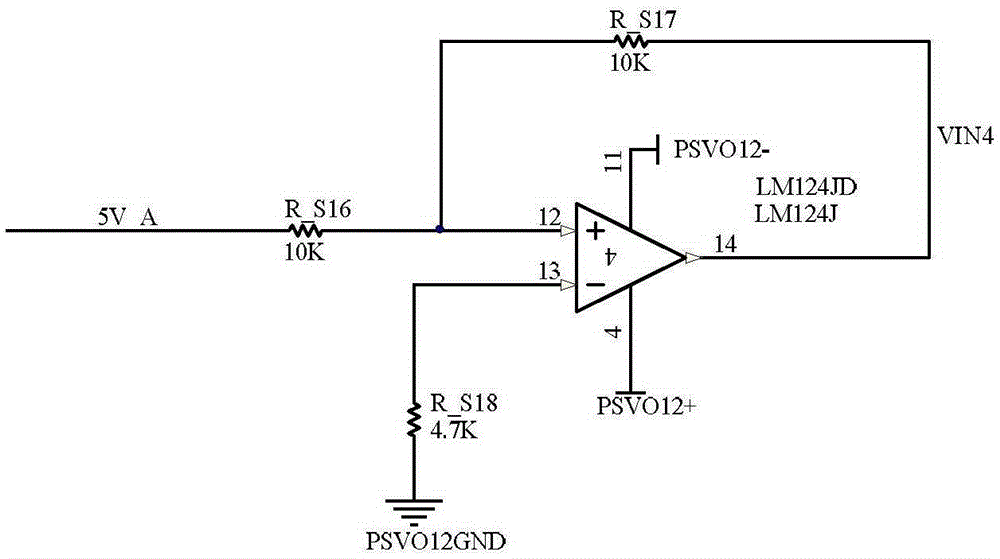
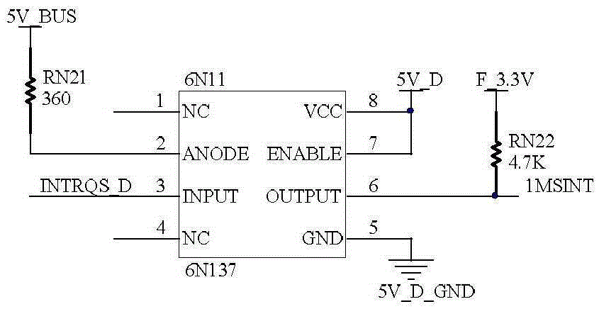
[0022] Specific implementation mode one: combine figure 1 , figure 2 with image 3 Describe this embodiment, the dual DSP redundant inertial platform controller described in this embodiment, the controller includes an AD conversion circuit 1, an IO circuit 2, a bus module 3, a power output module 4, a switching module 5, and a decision module 6 , the first DSP processor 7 and the second DSP processor 8;
[0023] The gyro digital signal output end of the AD conversion circuit 1 is connected with the gyro digital signal input ends of the first DSP processor 7 and the second DSP processor 8 at the same time, and the data output end of the IO circuit 2 is connected with the first DSP processor through an optocoupler at the same time. 7 is connected with the data input end of the second DSP processor 8, and the working state signal output end of the first DSP processor 7 passes through McBSP (MultichannelBufferedSerialPort, multichannel buffered serial port) and the working stat...
specific Embodiment approach 2
[0030] Specific implementation mode two: combination Figure 4 Describe this embodiment, this embodiment is a further limitation to the dual DSP redundant inertial platform controller described in the first embodiment, the decision module 6 includes an FPGA module, a detection module and a combinational logic circuit;
[0031] The FPGA module is used to determine whether the first DSP processor 7 breaks down by detecting the pulse signal of the GPIO pin of the first DSP processor 7, and sends the first DSP processor 7 failure judgment signals to the combinational logic circuit;
[0032] The detection module is used to detect whether the FPGA module fails, and sends an FPGA module failure judgment signal to the combinational logic circuit;
[0033] Combination logic circuit, for judging according to the first DSP processor 7 fault detection signal output by receiving the first DSP processor 7 fault judgment signal, the FPGA module fault judgment signal and the second DSP proces...
specific Embodiment approach 3
[0035] Specific implementation mode three: combination Figure 5 This embodiment is described. This embodiment is a further limitation of the dual DSP redundant inertial platform controller described in the second specific embodiment. The detection module is a monostable flip-flop circuit, and is realized by a monostable flip-flop SN54LS123J .
[0036] Such as Figure 7 As shown, a retriggerable monostable flip-flop 74LS123 is used to detect whether the FPGA module fails. When the input is a clock signal, the reverse output port of the flip-flop can generate a negative pulse, and the value of the external capacitor and resistance can be adjusted to set the width of the negative pulse. When the negative pulse width is greater than one period of the input clock and less than two periods, its reverse output port is no longer a negative pulse sequence, but a low level. When the input clock signal suddenly no longer changes from high to low, its reverse output port jumps to high...
PUM
 Abstract
Description
Claims
Application Information
 - R&D
- Intellectual Property
- Life Sciences
- Materials
- Tech Scout
- Unparalleled Data Quality
- Higher Quality Content
- 60% Fewer Hallucinations
Browse by: Latest US Patents, China's latest patents, Technical Efficacy Thesaurus, Application Domain, Technology Topic, Popular Technical Reports.
© 2025 PatSnap. All rights reserved.Legal|Privacy policy|Modern Slavery Act Transparency Statement|Sitemap|About US| Contact US: help@patsnap.com


