High-power railway communication signal control photo-electricity composite cable

A communication signal and optoelectronic integrated technology, applied in the direction of communication cables, insulated cables, twisted/quadruple twisted cables, etc., can solve the problems of train driving safety threats, construction inconvenience, individual wire breakage, etc. To achieve the effect of improving the actual performance and eliminating potential safety hazards

Active Publication Date: 2014-07-16
ZHONGTIAN TECH IND WIRE&CABLE SYST CO LTD
View PDF5 Cites 7 Cited by
  • Summary
  • Abstract
  • Description
  • Claims
  • Application Information

AI Technical Summary

Problems solved by technology

[0003] For a long time, in the use of various railway signal cables, when large current and long transmission distance control information transmission or power supply is required, multiple wire cores are used in parallel. This method not only brings inconvenience to construction, but more importantly Because it is a multi-core parallel connection, in practical applications, when one or several wires are broken, because the other wires are still connected, but because the line is in an abnormal state at this time, the transmission of control information and power supply have been stopped. Make the signal control or execution equipment in an abnormal state. In the long-term vibration environment of the cables laid along the railway line, this connection method is very easy to cause individual wires to break. When individual wires break, this serious accident haza

Method used


Image

  • High-power railway communication signal control photo-electricity composite cable
  • High-power railway communication signal control photo-electricity composite cable

Examples


Embodiment Construction

[0025] The technical solutions of the embodiments of the present invention will be clearly and completely described below in conjunction with the accompanying drawings of the present invention.

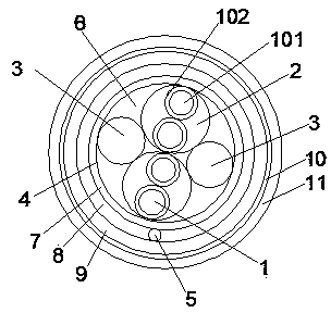
[0026] Such as figure 1 As shown, the high-power railway communication signal control optoelectronic integrated cable disclosed by the present invention is a wire pair 2 formed by twisting a single insulated core 1 or multiple insulated cores 1 at equal pitches, and multiple groups of different pitches The cable pair 2 and the optical communication unit 3 form a cable core 4, the gaps of the cable core 4 are filled with a water-blocking filling material 6, and the outside of the cable core 4 is sequentially covered with a water-blocking layer 7, a shielding layer 8, and an inner lining Layer 9, armor layer 10 and outer sheath 11.

[0027] Specifically: the insulated wire core 1 includes a conductor 101 and an insulating layer 102 covering the outside of the conductor 101, the conduct...


PUM

PropertyMeasurementUnit
Diameteraaaaaaaaaa

Abstract

The invention discloses a high-power railway communication signal control photo-electricity composite cable which comprises a cable core. The cable core comprises a plurality of wire pairs of single wires, twines, three-wire sets and star twisting sets which are twisted. The cable core is filled with water-stopping filler materials such as cable water-stopping factice and water-stopping yarn. The outer side of the cable core is sequentially coated with a water-stopping layer, a shielding layer, a lining layer, an armor layer and an outer protection layer. The wire pairs are formed by twisting two insulation wire cores and the like in an equal pitch mode, and the twisting pitches of every two adjacent wire pairs are different. Each insulation wire core is a conductor with the diameter ranging from 1.4mm to 1.8mm, and the outer side of each insulation wire core is coated with an insulating layer made of a crosslinked polyethylene material. The insulating layers are colored or printed with figure identifications in a spraying mode. The interior of the cable core comprises a photo-communication unit formed by a plurality of optical fibers, and the wire pairs or the filled single wires. An alarm wire is embedded in the shielding layer. According to the high-power railway communication signal control photo-electricity composite cable, the actual use performance is greatly improved on the premise of ensuring the original excellent electrical performance of the cable.

Description

technical field [0001] The invention relates to a railway cable, in particular to a high-power railway communication signal control photoelectric integrated cable. Background technique [0002] The existing railway digital signal cables meet the railway industry standards TB / T 2476 "Railway Signal Cable" and TB / T3100 "Railway Digital Signal Cable". Polyethylene insulated single wire construction. [0003] For a long time, in the use of various railway signal cables, when large current and long transmission distance control information transmission or power supply is required, multiple wire cores are used in parallel. This method not only brings inconvenience to construction, but more importantly Because it is a multi-core parallel connection, in practical applications, when one or several wires are broken, because the other wires are still connected, but because the line is in an abnormal state at this time, the transmission of control information and power supply have been...

Claims


Application Information

Patent Timeline
IPC IPC(8): H01B11/22H01B11/08H01B7/282
Inventor 梁斌周佳龙解向前马赟陆如泉范更生
Owner ZHONGTIAN TECH IND WIRE&CABLE SYST CO LTD
Why Eureka
Try Eureka