High bearing capacity composite material roller

A technology of composite materials and bearing columns, which is applied in the direction of bearing components, shafts and bearings, layered products, etc., can solve the problems of reduced bearing capacity, large plastic deformation, and high bearing strength

Inactive Publication Date: 2014-07-23
姜立平
View PDF11 Cites 8 Cited by
  • Summary
  • Abstract
  • Description
  • Claims
  • Application Information

AI Technical Summary

Problems solved by technology

As far as the bearing capacity of the cylinder is concerned, generally speaking, rollers made of materials with high hardness and strong rigidity have high allowable contact stress, but small elasticity, high brittleness, and poor impact resistance, so the bearing strength is not necessarily high.
The cylinder made of materials with

Method used


Image

  • High bearing capacity composite material roller
  • High bearing capacity composite material roller
  • High bearing capacity composite material roller

Examples


Embodiment 1

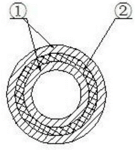
[0010] Embodiment 1: (as figure 1 shown)

[0011] This embodiment is a hollow cylinder, which is composed of three layers of spring steel 1 with high relative hardness and high elasticity and polyurethane material 2 with low relative hardness and high elasticity. Both ends of the column are closed by spring steel to form a complete cylinder. The surface layer of spring steel is backed by two layers of inner lining materials that are both rigid and soft, and the column will deform to a certain extent under high loads, thereby increasing the surface contact bearing area correspondingly, and then greatly improving the bearing capacity.

Embodiment 2

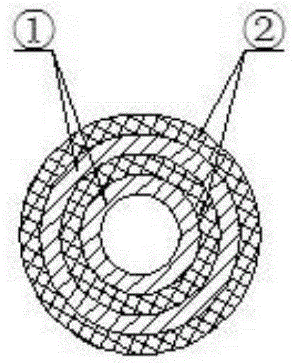
[0012] Embodiment 2: (as figure 2 shown)

[0013] This embodiment is a hollow cylinder, which is composed of bearing steel 1 with high relative hardness and high elasticity and modified nylon material 2 with low relative hardness and high elasticity. Its carrying mechanism is the same as that in Embodiment 1. The difference is that bearing steel is harder and more brittle than spring steel. Place it inside the second and fourth floors. Modified nylon is used for the surface layer and the third layer. It has both toughness and elasticity. And better strength. Carry out optimized design and rational layout. The noise reduction effect of the roller in bearings and or other rotating mechanisms is very obvious.

Embodiment 3

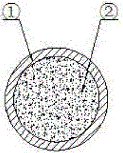
[0014] Embodiment 3: (as image 3 shown)

[0015] This embodiment is a solid cylinder, which is composed of stainless steel 304 material 1 with high relative hardness and high elasticity, and basalt fiber with a network structure with low relative hardness and high elasticity and modified PP material molten mixture composite material 2. Composite. The interior is a fusion composite material of basalt fiber and modified PP material, and the composite material itself is a column with high compressive strength. The outer surface is sealed and wrapped with stainless steel 304 material with high hardness and high elasticity, which further improves its carrying capacity.


PUM


Abstract

The invention relates to a multilayer type composite material roller, which is a circular column produced by compositing the materials with different hardness and different elasticity by interphase lamination. The high bearing capacity composite material roller fully keeps the allowable contact stress of a hard material. Under a support pad of a high elastomer material with low hardness, and the high compressive strength of a surface layer structure is preventing from being damaged. The whole circular column has certain elastic deformation, the bearing area is increased, and the corresponding bearing capacity is greatly increased. The problem that under outside force effect of the current common circular column, the contact area is small, so that the bearing capacity of the circular column is little, and the usage value and usage scope of the roller are reduced can be overcome. The novel laminated composite bearing roller has the advantages of large bearing capacity, simple structure, low cost, high cost performance, obvious noise reduction effect during a running process and wide application scope. The high bearing capacity composite material roller has considerable economic benefits and social benefits.

Description

technical field [0001] The invention relates to a column body, in particular to a multi-layer composite bearing column. It can be widely used in bearings and other rotating components with high load requirements. Background technique [0002] At present, ball bearings are generally not used for rotating components with high load requirements, and roller bearings are mostly used. Such as large-scale wind power generation and hydroelectric generators; diesel generators for marine and large-scale equipment; electric motors; industrial and mining machines, tunnel excavators; large winches; The rollers of these bearings are basically made of bearing steel or special superhard metal materials. Metal rollers and rollers with engineering plastic material structure are widely used. Cylinders of different materials reflect different physical and mechanical properties, such as: different densities, hardness, stiffness, strength, modulus of elasticity, coefficient of linear temperatu...

Claims


Application Information

Patent Timeline
IPC IPC(8): F16C33/34B32B1/08B32B15/095
Inventor 姜立平
Owner 姜立平
Why Eureka
Try Eureka