
Lead shielding block on end face of nuclear fuel channel in heavy water reactor nuclear power station and preparation method thereof

A nuclear reactor, lead shielding technology, applied in the directions of reactors, shielding, chemical instruments and methods, etc., can solve the problems of unsatisfactory anti-aging performance, difficult suspension, poor repeatability and stability, and achieve good environmental adaptability and long-term stability, better radiation protection and shielding, broad applicability and flexibility

Active Publication Date: 2014-07-23
SHENZHEN AIDUN RADIATION PROTECTION SAFETY EQUIP
View PDF5 Cites 4 Cited by
  • Summary
  • Abstract
  • Description
  • Claims
  • Application Information

AI Technical Summary

Problems solved by technology

[0005] 1. In order to avoid damage to the outer surface of the fuel channel, it needs to be operated very carefully, the suspension is difficult and time-consuming, and it does not meet the safety construction specifications of the factory;
[0006] 2. There are often large gaps between the lead plates, resulting in radiation leakage, resulting in radiation risks, and the overall radiation shielding effect of the integration of the entire end face cannot be achieved;
[0007] 3. Due to the hard surface of the lead plate, if the lead plate suspended at a high place accidentally falls, it is easy to injure the staff or cause damage to the equipment, and there is a great potential safety hazard;
[0008] 4. The lead plate is easy to cause surface contamination and is not easy to decontaminate during use, resulting in a large amount of scrap, and can cause a certain degree of pollution to the environment;
[0009] 5. The lead plate is easy to bend and deform during use, and it is difficult to restore the original shape, resulting in additional lead plate consumption and increasing the difficulty of operation during hoisting
[0013] (2) Although the finished product can maintain the original softness of the colloid, it cannot provide a large proportion of lead powder, so that the lead equivalent of the finished product is low. In order to provide enough lead equivalent, the amount of material needs to be increased, resulting in the weight of the shielding block made of this material is much larger than that of the lead block with the same lead equivalent
This will increase the load on the transportation and lifting equipment, and more importantly, it will increase the work intensity of the operators during the transportation and lifting of the shielding block, prolong the installation time of the shielding project, and increase the risk of operators being exposed to radiation;
[0014] (3) The production process of this material is cumbersome and complicated, and in the case of ensuring the same lead equivalent, more silicone rubber is required, so the manufacturing cost is high, which is not conducive to the product application and promotion
However, nuclear power plants have strict restrictions on the size, weight, and types of materials entering the station, and during the maintenance of nuclear power plants, the reactor building and other working tools and materials are transported intensively, so additional brackets or hangers will undoubtedly increase the end-face shielding The workload of the project will cause a shortage of transfer tool resources, and it will prolong the stay time of personnel and increase the risk of radiation
[0017] (2) Reversibility and anti-aging properties at high and low temperatures still cannot meet the requirements, resulting in poor reusability and stability, frequent replacement, and increased operating costs

Method used


Image

  • Lead shielding block on end face of nuclear fuel channel in heavy water reactor nuclear power station and preparation method thereof
  • Lead shielding block on end face of nuclear fuel channel in heavy water reactor nuclear power station and preparation method thereof
  • Lead shielding block on end face of nuclear fuel channel in heavy water reactor nuclear power station and preparation method thereof

Examples


Embodiment 1

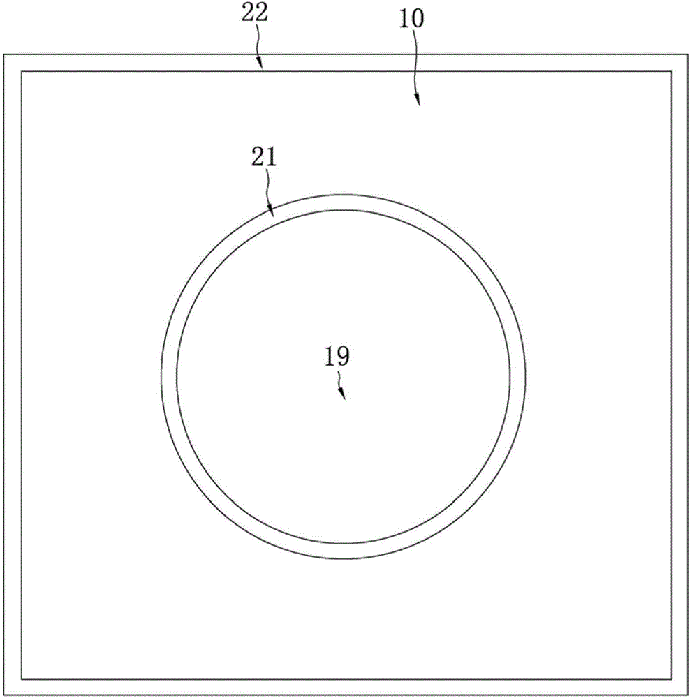
[0073] Such as figure 1 , figure 2 As shown, the lead shielding block on the end face of the nuclear fuel channel of the heavy water nuclear reactor nuclear power plant in this embodiment includes a multi-layer laminated lead foil 10, and the multi-layer laminated lead foil 10 is provided with positioning holes 19 for sheathing the lead shield block on the fuel channel. Silicone rubber layers 21 and 22 are provided on the outer side 13 of the multi-layer laminated lead foil 10 and the inner wall surface 14 of the positioning hole 19 . That is, the upper surface 11 and the lower surface 12 of the multi-layer laminated lead foil 10 are covered with a silicone rubber layer except for a part of the surface at the junction with the outer edge 13 and the inner wall surface 14 of the positioning hole 19, and most of the other surfaces are covered with a silicone rubber layer. Package covered. The silicon rubber layer of this embodiment is partially wrapped to cover important parts...

Embodiment 2

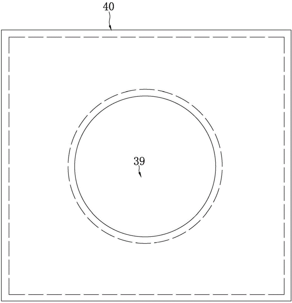
[0083] Such as image 3 , Figure 4 As shown, the difference between this embodiment and Embodiment 1 is that the silicone rubber layer of this embodiment adopts the "full wrapping" method, and the outer surface of the multi-layer laminated lead foil 30 is wrapped and covered by molding and / or bonding. All silicone rubber layers 40. That is, the exposed surfaces of the multilayer laminated lead foils are all covered by the silicone rubber layer, including the upper surface 31 of the uppermost lead foil, the lower surface 32 of the lowermost lead foil, the outer peripheral side 33 of the multilayer laminated lead foil, and the positioning holes The inner wall surface 34 of 39 is covered with a silicone rubber layer 40 . Provide comprehensive protection for multi-layer laminated lead foil, while strengthening the strength of the shielding block, it can also strengthen the integrity and return of the lead shielding block. For the preparation / manufacturing method of this embodi...

preparation example 1

[0087] Preparation Example 1: Preparation of multi-layer laminated lead foil

[0088] (1.1) Purification of lead

[0089] Heat the raw lead to 330°C, then raise the temperature to 370°C at a rate of 3°C / min to melt it, keep stirring during this period, and use a scraper to remove impurities floating on the upper part of the lead liquid until there are no floating objects.

[0090] (1.2) Lead casting

[0091] The lead liquid in step (1.1) was poured into the mold and cooled naturally to obtain a lead plate with a thickness of 1 cm.

[0092] (1.3) Lead plate cold rolling

[0093] Using cold rolling equipment, the lead plate in step (1.2) is repeatedly rolled at normal temperature until it is uniform and compact without air bubbles, to obtain a lead foil with a thickness of 0.1 mm;

[0094] (1.4) Lead foil overlay

[0095] Cut the lead foil of step (1.3) into the same size and cut a positioning hole of the same size in the center, and then stack them to obtain multi-layer s...


PUM

PropertyMeasurementUnit
thicknessaaaaaaaaaa
thicknessaaaaaaaaaa
thicknessaaaaaaaaaa

Abstract

The invention relates to a nuclear radiation protective supply and a preparation method of the nuclear radiation protective supply, in particular to a lead shielding block on the end face of a nuclear fuel channel in a heavy water reactor nuclear power station and a preparation method of the lead shielding block. The lead shielding block comprises multiple layers of overlying lead foil, wherein the lead foil is provided with locating holes, the fuel channel is sleeved with the lead shielding block through the locating holes, and silicone rubber layers are arranged on the outer side edges of the multiple layers of overlying lead foil and the inner wall faces of the locating holes. The preparation method of the lead shielding block comprises the steps of preparing the multiple layers of overlying lead foil, wrapping the multiple layers of overlying lead foil with silicone rubber, and conducting compression molding to obtain the lead shielding block. The lead shielding block does not damage the fuel channel and is light in self weight and easy to prepare, install and use.

Description

technical field [0001] The invention relates to a nuclear radiation protection product and a preparation method thereof, in particular to a lead shielding block on the end face of a nuclear fuel channel of a heavy water nuclear reactor nuclear power plant and a preparation method thereof. Background technique [0002] End face shielding plays a pivotal role in the radiation protection of nuclear power plants, especially heavy water reactor nuclear power plants. The "end face" here refers to the end of the fuel channel of the heavy water reactor nuclear power plant, which is composed of pipes of the same size. During the overhaul period of the heavy water brigade nuclear power plant, a large number of maintenance work was concentrated on the end face of the fuel channel and its surrounding areas, and the radiation dose level on the end face of the fuel channel was very high. According to statistics, about 80% of the external radiation of each overhaul came from the end face A...

Claims


Application Information

Patent Timeline
Patent Type & Authority Applications(China)
IPC IPC(8): G21F1/08G21F1/12B32B15/06
Inventor 孙霞凌宏志
Owner SHENZHEN AIDUN RADIATION PROTECTION SAFETY EQUIP
Learn More