
Waste gas treatment device and method for lubricating oil production line

A waste gas treatment device and lubricating oil technology, which is applied in the direction of combined devices, separation methods, chemical instruments and methods, etc., can solve problems such as safety production of devices that threaten personal safety, stench in the factory area, air pollution, etc., and achieve beautiful appearance and high processing efficiency High, reduce the effect of harmful substances

Active Publication Date: 2014-07-30
江苏司能润滑科技有限公司
View PDF5 Cites 19 Cited by
  • Summary
  • Abstract
  • Description
  • Claims
  • Application Information

AI Technical Summary

Problems solved by technology

Due to the complex composition of lubricating oil, the toxic substances produced during the production process mainly include non-methane total hydrocarbons (C14-C60 petroleum fractions, kerosene, solvent oil) or ethylene glycol factors, which exist in the tail gas of the blending unit. Generally, it is used to vent to the sky, and the discharge to the sky will produce a bad smell in the factory area, causing great pollution to the air, and threatening personal safety and safe production of equipment.

Method used


Image

  • Waste gas treatment device and method for lubricating oil production line

Examples


Embodiment Construction

[0034] The present invention is described in further detail now in conjunction with accompanying drawing. These drawings are all simplified schematic diagrams, which only illustrate the basic structure of the present invention in a schematic manner, so they only show the configurations related to the present invention.

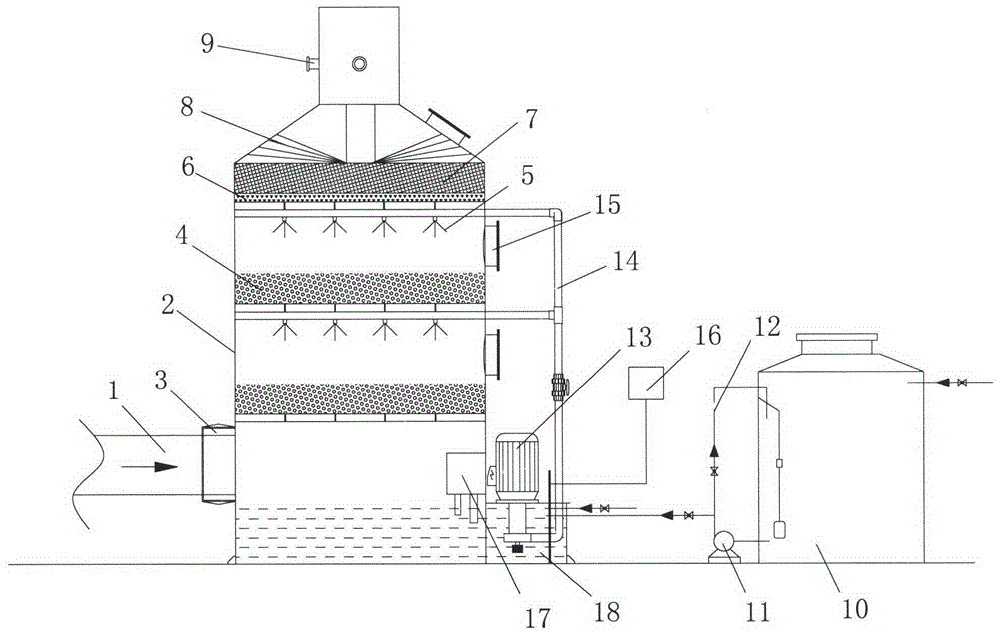
[0035] Such as figure 1 As shown, an exhaust gas treatment device for a lubricating oil production line, including a cylinder 2, a glass fiber filter 3, a nozzle 5, a packing layer 4, an activated carbon adsorption layer 7, a circulating water pump 13, a liquid storage tank 18 and a dosing box 10. The glass fiber filter 3 is arranged at the air inlet at the lower end of the cylinder body 2, the packing layer 4 is fixed in the middle of the cylinder body 2, the nozzle 5 is correspondingly arranged above the packing layer 4, and the activated carbon adsorbs The layer 7 is correspondingly arranged above the nozzle 5, the circulating water pump 13 is arranged on ...


PUM


Abstract

The invention relates to a waste gas treatment device and method for a lubricating oil production line. The waste gas treatment device comprises a cylinder body, a glass fiber filter, spray heads, filler layers, an active carbon adsorption layer, a circulating water pump, a liquid storage tank and a dosing tank, wherein the glass fiber filter is arranged at an air inlet in the lower end of the cylinder body, the filler layers are fixed in the middle in the cylinder body, the spray heads are correspondingly arranged above the filler layers, the active carbon adsorption layer is correspondingly arranged above the spray heads, the circulating water pump is arranged on the liquid storage tank and is connected with the spray heads, and the dosing tank is communicated with the interior of the liquid storage tank through a dosing pump. According to the waste gas treatment device and the waste gas treatment method, by carrying out several procedures of water absorption, water removal and active carbon adsorption, harmful substances in the waste gas generated in a production process of lubricating oil can be greatly reduced and are far lower than national discharge standards; the device has the advantages of low resistance, low energy consumption, low noise, high processing efficiency, high corrosion resistance, high strength, convenience in dismounting and maintaining, lightness, durability and the like.

Description

technical field [0001] The invention relates to the field of lubricating oil production, in particular to a waste gas treatment device and a waste gas treatment method for a lubricating oil production line. Background technique [0002] The use of lubricating oil is one of the important means to control friction and reduce wear. With the continuous development of the national economy, the consumption of lubricating oil in our country is increasing. Due to the complex composition of lubricating oil, the toxic substances produced during the production process mainly include non-methane total hydrocarbons (C14-C60 petroleum fractions, kerosene, solvent oil) or ethylene glycol factors, which exist in the tail gas of the blending unit. Generally, it is used to vent to the sky, and the discharge to the sky will produce a bad smell in the factory area, causing great pollution to the air, and threatening personal safety and safe production of the device. Therefore, this part of th...

Claims


Application Information

Patent Timeline
Patent Type & Authority Applications(China)
IPC IPC(8): B01D50/00B01D53/14B01D53/18B01D53/04
Inventor 黄富云贾汝涛杜茂金陈丽萍吴益俊
Owner 江苏司能润滑科技有限公司
Learn More