Supercharge Your Innovation With Domain-Expert AI Agents!

Metal rubber blank weaving equipment and special cover mechanism

A metal rubber and cover plate technology, applied in applications, household appliances, other household appliances, etc., can solve the problems of poor hook strength, high rejection rate, delamination and cracking, etc. rate reduction effect

Inactive Publication Date: 2016-01-20
PEOPLES LIBERATION ARMY ORDNANCE ENG COLLEGE
View PDF8 Cites 0 Cited by
  • Summary
  • Abstract
  • Description
  • Claims
  • Application Information

AI Technical Summary

Problems solved by technology

At present, in the preparation process of metal rubber, the helical winding process is generally used to prepare blanks. This process is suitable for the preparation of metal rubber components with conventional sizes and simple configurations. For thin-walled bushings with large axial dimensions For rubber components, if the blank is still prepared by the helical wire winding process, it will not only bring difficulties to the subsequent stamping die design and stamping forming process, but also because the hooking strength between the metal wire helixes inside the metal rubber is poor, resulting in metal after stamping Rubber components are prone to delamination and cracking, which seriously affects the molding quality and technical performance of the product, the scrap rate is extremely high, and the service life is greatly reduced

Method used


Image

  • Metal rubber blank weaving equipment and special cover mechanism
  • Metal rubber blank weaving equipment and special cover mechanism
  • Metal rubber blank weaving equipment and special cover mechanism

Examples


Embodiment Construction

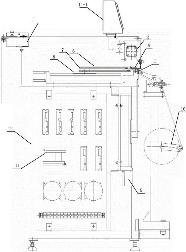
[0057] like Figure 1~Figure 3 As shown, the present invention includes a constant pitch stretching mechanism 1, a wiring mechanism 2, an auxiliary hook 3 (not shown), a horizontal chute plate 4, a vertical chute plate 5, a cover plate mechanism 6, a hook mechanism 7, and a horizontal auxiliary mechanism 8. Vertical auxiliary mechanism 9 , winding mechanism 10 , control system 11 and frame 12 .

[0058] like Figure 4~Figure 6 As shown, the constant pitch stretching mechanism 1 includes: a wire wheel 1-1, a damper 1-2, a damping wheel 1-3, a damping pressing wheel 1-4, a pressing device 1-5, and an active wire worm wheel 1 -6. The driven wire pay-off wheel 1-7 and the stretching motor 1-8.

[0059] The dense-turn metal wire helix is ​​fed into the constant-pitch stretching mechanism 1 through the wire wheel 1-1. Under the control of the control system 11, it cooperates with the wiring mechanism 2 to realize the constant-pitch stretching of the dense-turn metal wire helix.

...


PUM


Abstract

The invention discloses metal rubber blank weaving equipment and a special cover plate mechanism. The weaving equipment comprises a frame, wherein a constant-pitch stretching mechanism, a thread arranging mechanism, an auxiliary hook, the cover plate mechanism, a crochet hook mechanism, a horizontal auxiliary mechanism, a horizontal sliding chute plate, a vertical auxiliary mechanism, a vertical sliding chute plate, a rolling-up mechanism and a control mechanism are mounted on the frame; the constant-pitch stretching mechanism is used for stretching dense metal-wire spiral threads; the thread arranging mechanism is used for arranging the stretched metal-wire spiral threads onto crochet hooks; the auxiliary hook is used for starting the first line of a spiral thread mesh; the cover plate mechanism, the crochet hook mechanism, the horizontal auxiliary mechanism, the horizontal sliding chute plate, the vertical auxiliary mechanism and the vertical sliding chute plate are used for weaving the spiral threads into the spiral thread mesh; the rolling-up mechanism is used for rolling up the woven spiral thread mesh into a roll; the control system is used for controlling operation of the constant-pitch stretching mechanism, the thread arranging mechanism, the cover plate mechanism, the crochet hook mechanism, the horizontal auxiliary mechanism, the vertical auxiliary mechanism and the rolling-up mechanism so as to perform constant-pitch stretching on the dense metal-wire spiral threads and then control the weaving process of the spiral threads. The weaving equipment can greatly improve the hooking and connecting strength of metal wires in the metal rubber.

Description

technical field [0001] The invention relates to a device for preparing metal rubber blanks, in particular to a numerically controlled full-automatic metal rubber blank weaving equipment. Background technique [0002] Metallic rubber is a new type of elastic damping material. It is prepared from thin metal wires of different grades and wire diameters through a series of processes such as helical wire winding, helical wire stretching at a fixed pitch, blank preparation, cold stamping, and post-processing. Under the action of load, the material will have friction, sliding and extrusion between the helixes of the metal wire, which can dissipate a large amount of vibration energy. It has rubber-like high elasticity, large damping characteristics and excellent physical and mechanical properties of metal, so named. Metallic rubber has significant advantages such as non-volatile in vacuum, not afraid of radiation environment, high / low temperature resistance, corrosion resistance, l...

Claims


Application Information

Patent Timeline
Patent Type & Authority Patents(China)
IPC IPC(8): B21F27/02
Inventor 白鸿柏路纯红李冬伟曹凤利
Owner PEOPLES LIBERATION ARMY ORDNANCE ENG COLLEGE
Features
  • R&D
  • Intellectual Property
  • Life Sciences
  • Materials
  • Tech Scout
  • Unparalleled Data Quality
  • Higher Quality Content
  • 60% Fewer Hallucinations
Learn More