Electromagnetic riveting equipment adopting reciprocating type electromagnetic launching technology

An electromagnetic riveting and reciprocating technology, applied in the field of mechanical connection, can solve the problems of heat generation, large size and weight of electromagnetic riveting equipment, and low energy utilization rate, and achieve the effects of small heat generation, improved energy utilization rate, and light weight.

Active Publication Date: 2014-07-30
BEIJING AERONAUTICAL MFG TECH RES INST
View PDF4 Cites 9 Cited by
  • Summary
  • Abstract
  • Description
  • Claims
  • Application Information

AI Technical Summary

Problems solved by technology

[0006] In order to solve the problems of large volume and weight, low energy utilization rate and heat generation of electromagnetic riveting equipment, and also to obtain lighter and long-life riveting and installation technology, the present invention proposes an electromagnetic riveting technology using reciprocating electromagnetic launching technology. Riveting equipment

Method used


Image

  • Electromagnetic riveting equipment adopting reciprocating type electromagnetic launching technology

Examples


Embodiment

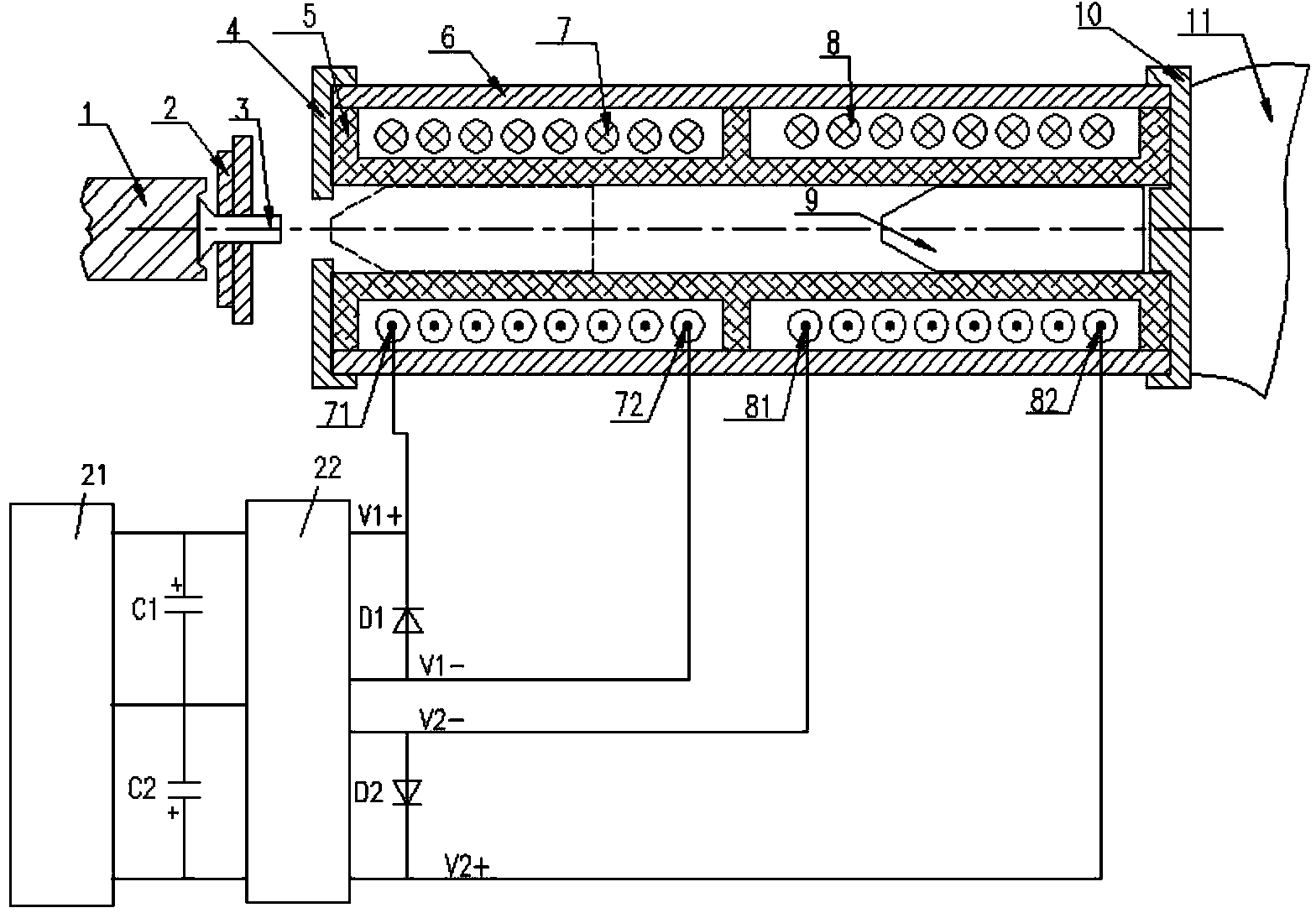
[0021] In this embodiment, a riveting gun was designed and manufactured according to the schematic diagram of the riveting gun, and a power supply was manufactured according to the schematic diagram of the power supply, and a riveting test was carried out with a top iron. The riveting system power supply includes a group of pulse capacitors with a rated voltage of 450 volts and a rated capacitance of 4700 microfarads connected in parallel to form a main coil discharge capacitor bank, and the auxiliary coil capacitor bank uses several capacitors with a rated voltage of 450 volts and a rated capacity of 2200 microfarads; The two discharge circuits use high-power semiconductor switches to control the discharge of the discharge circuit; the two charging circuits use a resonant soft switch to control the charge.

[0022] In the implementation, first charge the auxiliary coil capacitor to the set voltage, then discharge to pull the mover back to the initial position; then charge the ...


PUM


Abstract

The invention belongs to the technical field of mechanical connection and relates to electromagnetic riveting equipment adopting a reciprocating type electromagnetic launching technology for aeronautic and astronautic engineering. An electromagnetic launching mechanism is introduced into the field of electromagnetic riveting; through time division discharge of two groups of coils, riveting coils enable a metal punch to be accelerated to hit a riveting mold for riveting; after return coils accomplish riveting, the metal punch returns to an initial position. A riveting power head reciprocating motion method is implemented. By using the method, electric energy passing through the coils can entirely act on metal punch rotors in the coils, so that the metal punch can be continuously accelerated in a magnetic field to gain kinetic energy. Thus, the utilization rate of energy can be greatly increased; after gaining the maximum kinetic energy, the metal punch hits the riveting mold to realize riveting, and the energy in the coils is entirely used for accelerating the metal punch. According to the electromagnetic riveting equipment, the utilization rate of the energy is greatly increased. The electromagnetic riveting equipment is small in size, light in weight, small in heating, easy to operate and safer.

Description

technical field [0001] The invention belongs to the technical field of mechanical connection, and relates to an electromagnetic riveting device using reciprocating electromagnetic emission technology used in aviation and aerospace engineering. Background technique [0002] In the manufacturing and assembly process of aviation and aerospace engineering products, a large number of rivets need to be riveted. The main riveting methods are: hammer riveting, pressure riveting, electromagnetic riveting. [0003] The hammer riveting method using compressed air as the power source is the most common. However, the recoil and noise generated by this riveting method are large, the working conditions are poor, and the riveting quality is not easy to control. [0004] The pressure riveting method uses static pressure to deform the rivet, and the riveting quality is relatively stable. However, the riveting machine has a large volume and cannot be used in closed parts, and it is inconven...

Claims


Application Information

Patent Timeline
Patent Type & Authority Applications(China)
IPC IPC(8): B21J15/24
CPCB21J15/24
Inventor 高明辉肖庆东许国康秦玉波
Owner BEIJING AERONAUTICAL MFG TECH RES INST
Why Eureka
Try Eureka