Continuous carbonization furnace

A technology of carbonization furnace and rotary furnace, applied in the field of continuous carbonization furnace, which can solve the problems of low temperature of wood gas extraction, pollution of equipment and environment, low thermal efficiency, etc., and achieve the effect of improving energy utilization rate, solving easy blockage, and strong adaptability

Inactive Publication Date: 2014-07-30
NANJING DEMIN NEW ENERGY TECH
View PDF2 Cites 3 Cited by
  • Summary
  • Abstract
  • Description
  • Claims
  • Application Information

AI Technical Summary

Problems solved by technology

[0003] Chinese Patent CN102504835A "Biomass Carbonization Furnace" discloses a biomass carbonization furnace that can not only increase the carbonization speed of biomass raw materials but also improve the carbonization quality of biomass raw materials, but this invention does not make full use of the wood gas produced by carbonization, resulting in energy waste, thermal inefficiency
However, this equipment has the following shortcomings: 1. It is only an external thermal carbonization method, without internal thermal contact between high-temperature flue gas and biomass raw materials, and the carbonization efficiency is low
2. The traditional anaerobic pyrolysis process is adopted, and the yield of charcoal and combustible gas cannot be adjusted
3. The extraction temperature of wood gas is low, and it is easy to condense into wood tar, causing pipeline blockage, polluting equipment and the environment

Method used


Image

  • Continuous carbonization furnace
  • Continuous carbonization furnace

Examples


Embodiment Construction

[0045] In order to describe the technical content, structural features, achieved goals and effects of the present invention in detail, the following will be described in detail in conjunction with the embodiments and accompanying drawings.

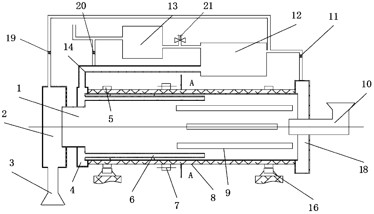
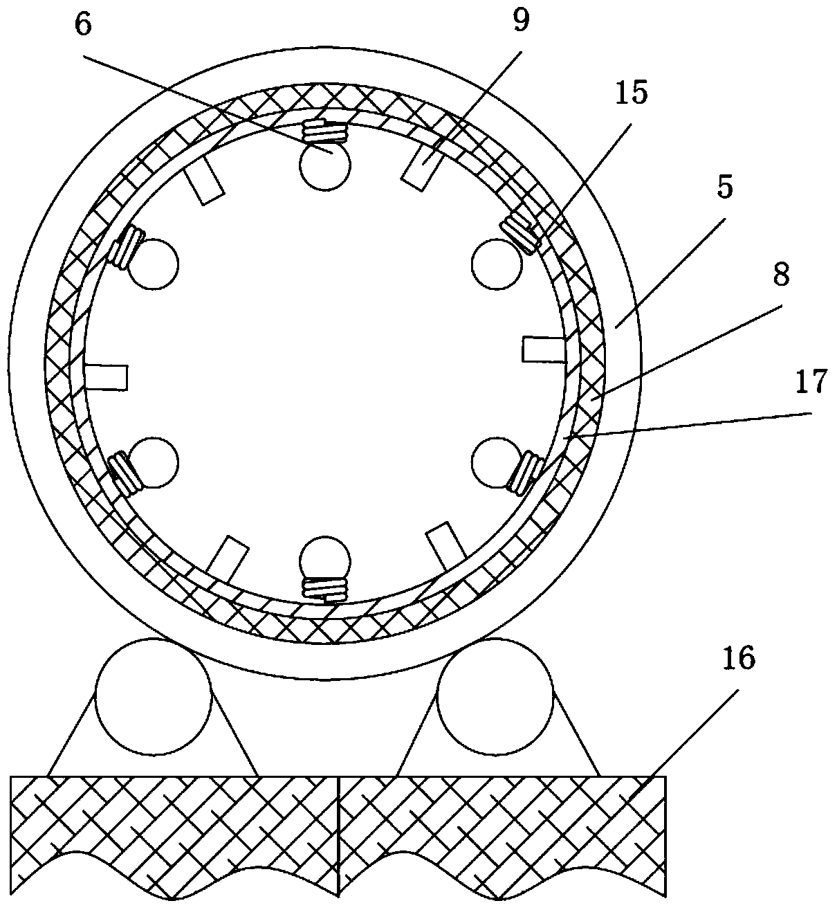
[0046] see figure 1 and figure 2 , figure 1 It is a structural diagram of a continuous carbonization furnace according to an embodiment of the present invention; figure 2 for figure 1 A-A sectional view of the medium continuous carbonization furnace.

[0047] The continuous carbonization furnace includes a rotary furnace 1, and the two ends of the rotary furnace 1 are respectively provided with a blanking device 3 and a feeding device 10; the continuous carbonization furnace also includes a combustion chamber 12 and a flue gas channel.

[0048] The inner cavity of the rotary furnace 1 is provided with a flue gas heat exchange channel and a flue gas return port. The channel wall of the flue gas heat exchange channel is a heat conducti...


PUM


Abstract

The invention provides a continuous carbonization furnace which comprises a rotary furnace, a feeding device and a blanking device, wherein the feeding device and the blanking devices are respectively connected to the two ends of the rotary furnace; the carbonization furnace also comprises a combustion chamber, a flame path and a flue gas channel; an inner cavity of the rotary furnace is provided with a flue gas heat exchange channel, the channel wall of the flue gas heat exchange channel is a heat-conducting wall, the flue gas heat exchange channel is provided with a flue gas inlet and a flue gas outlet, the flue gas inlet of the flue gas heat exchange channel is communicated with the combustion chamber through the flame path, and the flue gas heat exchange channel extends from the flue gas inlet to the flue gas outlet along a direction from a blanking port to a feed inlet; the flue gas channel is communicated with the combustion chamber and the inner cavity of the rotary furnace; the inner cavity of the rotary furnace comprises an outer hot area and an inner hot area, the area on one side of the inner cavity of the rotary furnace and provided with the flue gas heat exchange channel is the outer hot area, and the area on the other side is the inner hot area. The continuous carbonization furnace disclosed by the invention is small in occupied land and low in cost, solves a problem that pipelines are easily blocked, and improves the utilization rate of energy, and also can flexibly adjust the proportion of pyrolysis products, therefore, the continuous carbonization furnace has strong adaptability to production requirements.

Description

technical field [0001] The invention relates to the field of energy utilization, in particular to a continuous carbonization furnace, which is suitable for the fields of small-scale and high-efficiency biomass charcoal production and industrial heat supply. Background technique [0002] With the gradual depletion of fossil energy and the deterioration of the environment at the end of the 20th century, the international community began to pay attention to the development of new energy, especially the research and development of biomass energy. Biomass energy has the characteristics of large reserves, renewable, storable and replaceable, carbon neutral and clean, and has unique advantages in energy utilization and environmental protection. [0003] Chinese Patent CN102504835A "Biomass Carbonization Furnace" discloses a biomass carbonization furnace that can not only increase the carbonization speed of biomass raw materials but also improve the carbonization quality of biomass ...

Claims


Application Information

Patent Timeline
IPC IPC(8): C10B1/10
Inventor 陈琛陈俊
Owner NANJING DEMIN NEW ENERGY TECH
Why Eureka
Try Eureka