Control device of micro-ring optical switch

A control device and optical switch technology, applied in the coupling of optical waveguide, electrical program control, program control in sequence/logic controller, etc., can solve the difficulties of circuit packaging, complex manufacturing process, functional components and their peripheral control circuits Many problems, to achieve the effect of overcoming deterioration, reducing process requirements, and reducing production process requirements

Inactive Publication Date: 2014-07-30
UNIV OF ELECTRONICS SCI & TECH OF CHINA
View PDF5 Cites 22 Cited by
  • Summary
  • Abstract
  • Description
  • Claims
  • Application Information

AI Technical Summary

Problems solved by technology

At present, there are two main methods to solve the temperature sensitivity of the micro-ring optical switch: one is to keep the micro-ring resonator at a constant temperature by integrating a micro-heater on the micro-ring resonator. With the increase of the number of integrated microrings, the number of pins will become more and more, and the circuit packaging will become more and more difficult; another method to reduce the temperature dependence of the microring optical switch is to use a thermal balance interferometer structure embedded in the microring or in the package. The negative thermo-optic coefficient material is used in the layer. The disadvantage of this scheme is that there are many functional elements on the chip and its peripheral control circuits, and its manufacturing process is complicated.

Method used


Image

  • Control device of micro-ring optical switch
  • Control device of micro-ring optical switch
  • Control device of micro-ring optical switch

Examples


Embodiment

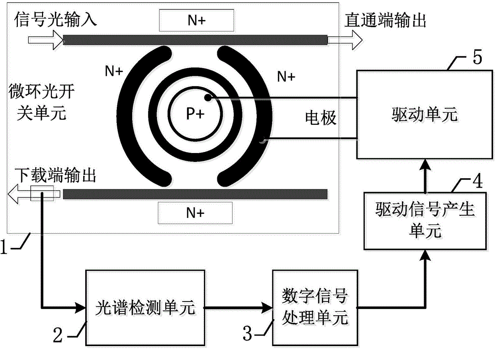
[0027] figure 1 It is a structure diagram of a specific embodiment of the control device of the micro-ring optical switch of the present invention.

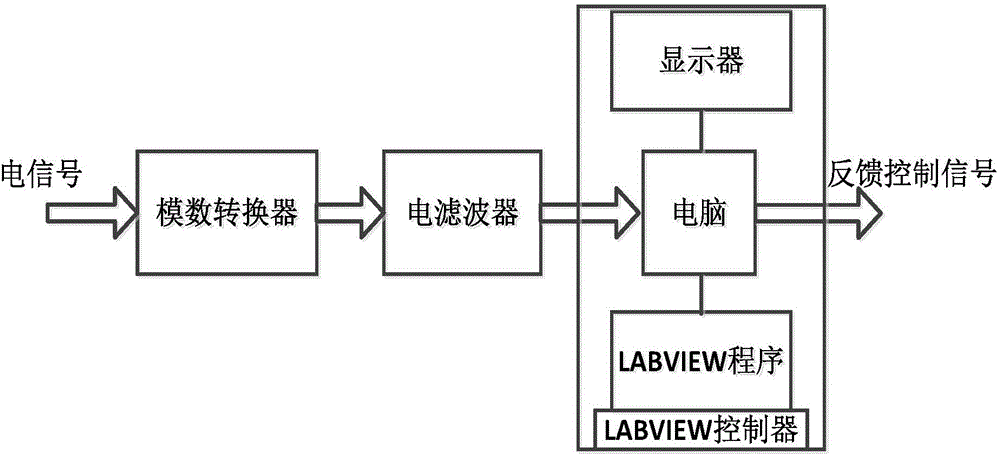
[0028] figure 2 yes figure 1 Block diagram of the digital signal processing unit shown.

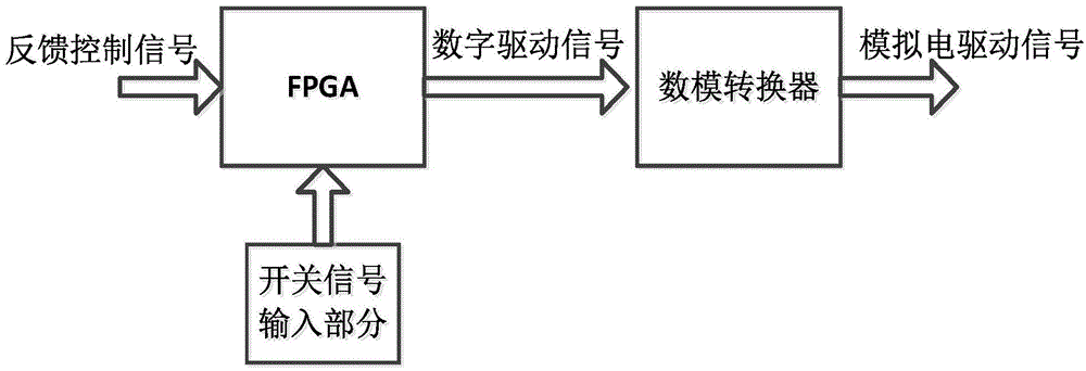
[0029] image 3 yes figure 1 The structural block diagram of the driving signal generating unit shown.

[0030] Figure 4 yes figure 1 Schematic diagram of the drive signal generation unit for generating digital electric drive signals.

[0031] In this example, if figure 1 As shown, the control device of the microring optical switch of the present invention includes: a microring optical switch unit 1, including a microring, an input channel waveguide, an output channel waveguide and a PIN structure; the input channel waveguide and the output channel waveguide are located on both sides of the microring Coupled with the microring, the optical signal is input from the input channel waveguide port. When the optical signal meets the res...


PUM


Abstract

The invention discloses a control device of a micro-ring optical switch. An optical signal is sent to a spectrum detection unit after being processed through a micro-ring optical switch unit. The spectrum detection unit detects spectrum changes and conducts photoelectric signal conversion. An electrical signal output by the spectrum detection unit sequentially passes through a digital signal processing unit and a driving signal generating unit so that an appropriate driving signal can be generated. Micro-ring optical switch driving and temperature control over a chip are completed through a driving unit. In this way, no cryogenic temperature compensation is needed by the micro-ring optical switch, the defect that the micro-ring optical switch is degraded when affected by temperature drifting is overcome, the process requirement for manufacturing is lowered, and the control device can be applied to high-speed exchange networks.

Description

technical field [0001] The invention belongs to the technical field of optical fiber communication, and more specifically relates to a control device for a micro-ring optical switch. Background technique [0002] In the process of social informatization, optical fiber communication network technology has played an important role; all-optical switching technology can ensure the reliability of the network and provide a flexible signal routing platform. Although the existing communication systems use electronic switching technology, the developing An all-optical network requires optical switching technology to achieve high network speed and protocol transparency. Optical switching technology provides dynamic optical domain processing for the high-speed information flow entering a node. Only the information belonging to the node and its subnet is added and dropped, and then handed over to the electrical switching equipment for further processing. This can overcome the capacity b...

Claims


Application Information

Patent Timeline
Patent Type & Authority Applications(China)
IPC IPC(8): G05B19/04
CPCG02B6/42G05B19/04
Inventor 武保剑王利辉邱昆文峰胡钢廖明乐张中一
Owner UNIV OF ELECTRONICS SCI & TECH OF CHINA
Why Eureka
Try Eureka