Laser cutting plate waste material separation part sorting system

A laser cutting and sorting system technology, applied in solid separation, magnetic separation, laser welding equipment, etc., can solve problems such as a large number of unfavorable suction cups, easy to fall into dust and debris, and reduce reliability.

Active Publication Date: 2014-08-06
JIANGSU JINFANGYUAN CNC MACHINE CO LTD
View PDF8 Cites 24 Cited by
  • Summary
  • Abstract
  • Description
  • Claims
  • Application Information

AI Technical Summary

Problems solved by technology

[0003] At present, the international laser cutting cutting and sorting schemes are all completed by vacuum system, that is, the suction cup is used to suck up the parts from above, and then move to the sorting table for sorting. Because the laser cutting process inevitably requires the use of micro-connection technology , that is, there is a tiny connection between the part and the scrap but not completely cut, only a small connection is kept to prevent the plate from lifting and affecting the cutting process, but the micro connection will increase the difficulty of parts sorting, and there is no suitable solution yet According to the solution, if a suction cup is also set under the workpiece to absorb the waste of the workpiece, it can work together with the suction cup on the upper part to separate the two parts from the waste, but this structure will have the following problems: first, the suction cup is set below, The surface of the suction cup is easy to fall into dust, sundries, etc., and it is easy to leak air, which reduces the reliability
Second, when the suction cup is working, the unevenness of the surface of the plate will easily lead to air leakage. Air leakage not only reduces the suction force, but also generates a lot of noise
Third, the suction cup needs to have a large enough suction area and negative pressure to generate a large enough suction force, which is not conducive to the large number of suction cups.
Fourth, when each suction cup needs to be independently controlled, it requires a large number of solenoid valves and vent pipes, which are difficult to install and arrange. The number of suction cups is often insufficient, and refined production cannot be carried out.

Method used


Image

  • Laser cutting plate waste material separation part sorting system
  • Laser cutting plate waste material separation part sorting system
  • Laser cutting plate waste material separation part sorting system

Examples


Embodiment Construction

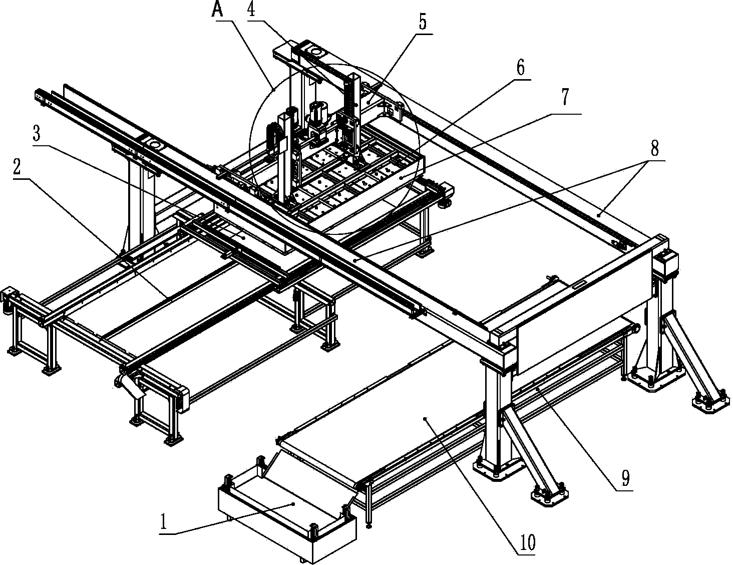
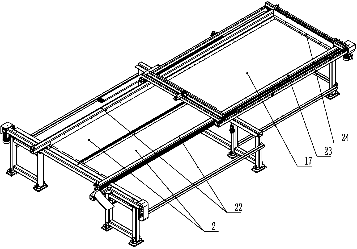
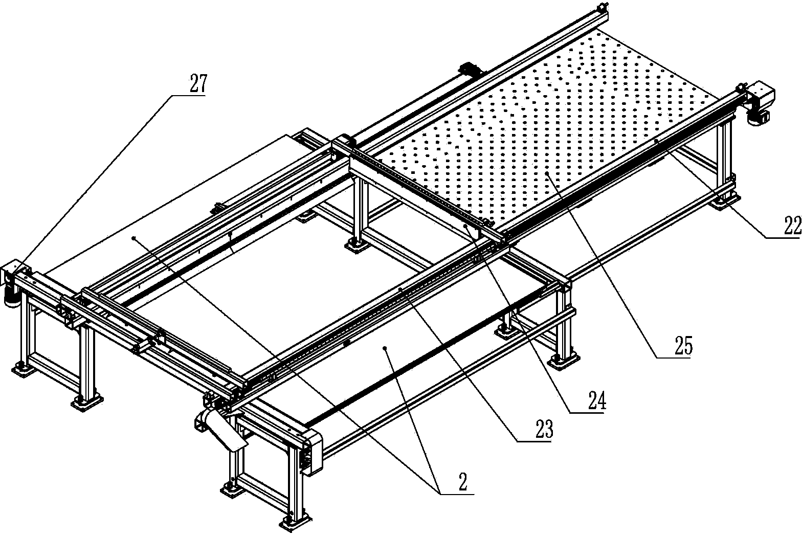
[0021] As shown in the figure, it is a laser cutting plate waste separation and parts sorting system. Its structure includes two support beams 8 arranged in parallel, a beam 5 is connected between the support beams 8, and a horizontal movement mechanism 15 is arranged at both ends of the beam 5 It is connected with the support beam 8 so that the cross beam 5 can slide horizontally along the support beam 8. The lifting column 4 is connected to the cross beam 5 through the lifting transmission mechanism. The lifting transmission mechanism includes a servo motor 20. Case 14 both sides protrudes transmission shaft 19 respectively, and transmission shaft 19 is rotatably connected on the sliding support 11, and lifting column 4 is provided with rack 12 and column guide rail 13 respectively, and sliding support 11 is provided with and column guide rail 13 slides. The connected column slider, the shaft end of the transmission shaft 19 is provided with a gear to mesh with the rack 12; t...


PUM


Abstract

The invention discloses a laser cutting plate waste material separation part sorting system in the field of laser cutting machines. The laser cutting plate waste material separation part sorting system comprises two parallelly arranged supporting beams. A beam capable of moving horizontally is movably connected between the two supporting beams. The beam is connected with a lifting column through a lifting transmission mechanism, the lower portion of the lifting column is connected with a blanking mechanical hand, a waste material separation table and a sorting working table are arranged below the supporting beams and correspond to the blanking mechanical hand, the blanking mechanical hand comprises a rectangular frame, a support is arranged in the frame, a mounting plate is arranged below the support, a plurality of liftable electric permanent magnets with suction surfaces downward are installed on the lower side of the mounting plate through an elastic mechanism, the waste material separation table is provided with a plurality of fixed electric permanent magnets with suction surfaces upward, and every liftable electric permanent magnet and every fixed electric permanent magnet can supply power independently. Parts and waste materials are separated more reliably, the parts are sorted conveniently, and the laser cutting plate waste material separation part sorting system is high in efficiency and suitable for laser cutting automation of carbon steel plates.

Description

technical field [0001] The invention relates to a laser cutting machine, in particular to a blanking device of the laser cutting machine. Background technique [0002] Laser cutting is to use laser as a processing method to cut metal or non-metal plates, and can process straight lines and curves of any shape on flat plates. In order to improve the efficiency and automation level of laser cutting and reduce the labor intensity of workers, laser cutting flexible production line (FMS) came into being and is widely used in electrical manufacturing, automobiles, instrument switches, textile machinery, transportation machinery, home appliance manufacturing, and elevator equipment manufacturing. , food industry, decoration and advertising, and laser processing stations. [0003] At present, the laser cutting cutting and sorting schemes in the world are all completed by vacuum system, that is, the suction cup is used to suck up the parts from above, and then move to the sorting tab...

Claims


Application Information

Patent Timeline
Patent Type & Authority Applications(China)
IPC IPC(8): B23K26/70B23K26/38B03C1/16
CPCB03C1/16B23K26/38B23K2101/18
Inventor 周庆欧阳斌张礼峰桑伟峰陈树明何承义夏建斌
Owner JIANGSU JINFANGYUAN CNC MACHINE CO LTD
Why Eureka
Try Eureka