Energy saving device for directly recycling waste heat from condenser of power plant to supply heat and energy saving method

An energy-saving device and condenser technology, applied in household heating, heating methods, heating systems, etc.

Inactive Publication Date: 2014-08-06
SHENYANG MAPLE ENERGY TECH
View PDF4 Cites 4 Cited by
  • Summary
  • Abstract
  • Description
  • Claims
  • Application Information

AI Technical Summary

Problems solved by technology

According to the common sense of science and technology, it can be known that the benefits obtained by any indirect method are always lower than those obtained by the direct method

Method used


Image

  • Energy saving device for directly recycling waste heat from condenser of power plant to supply heat and energy saving method
  • Energy saving device for directly recycling waste heat from condenser of power plant to supply heat and energy saving method

Examples


Embodiment 1

[0018] Embodiment 1 (water cooling system power plant)

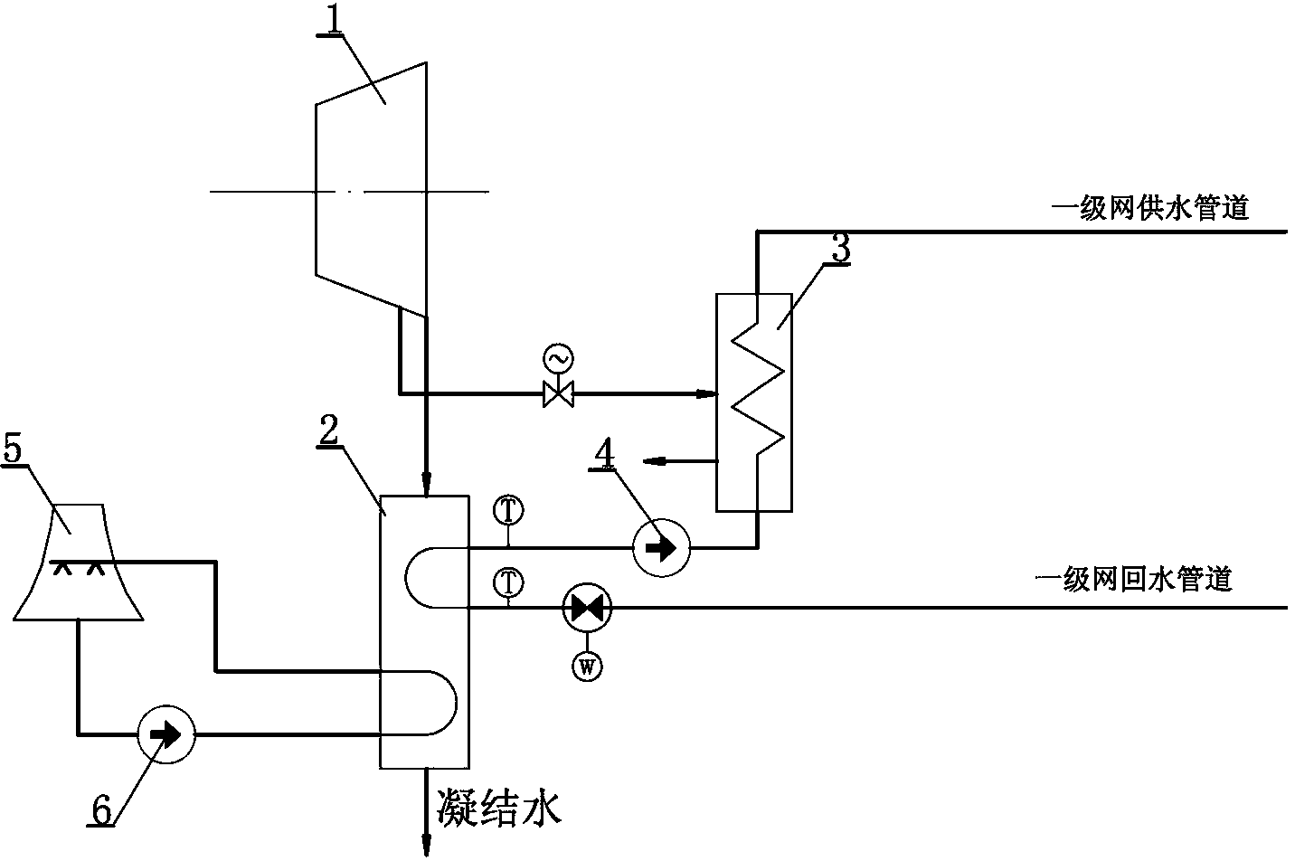
[0019] Such as figure 1 As shown, an energy-saving device that directly recovers waste heat from the condenser of a power plant for heat supply, is provided with a main heat exchanger 3 for heating on the primary heating network, and the heat source inlet of the main heat exchanger 3 is connected to the steam turbine 1 of the power plant The steam extraction port is connected; the exhaust port of the steam turbine 1 of the power plant is connected with the inlet of the condenser 2; the hot water heat exchange channel is set in the condenser 2, and the return water pipe of the primary network is connected with the inlet of the hot water heat exchange channel , the outlet of the hot water heat exchange channel is connected to the inlet of the main heat supply heat exchanger 3 through the heating main circulation pump 4, and the return water pipe of the primary network is connected to the hot water heat exchange channel of ...

Embodiment 2

[0026] Embodiment 2 (air cooling system power plant)

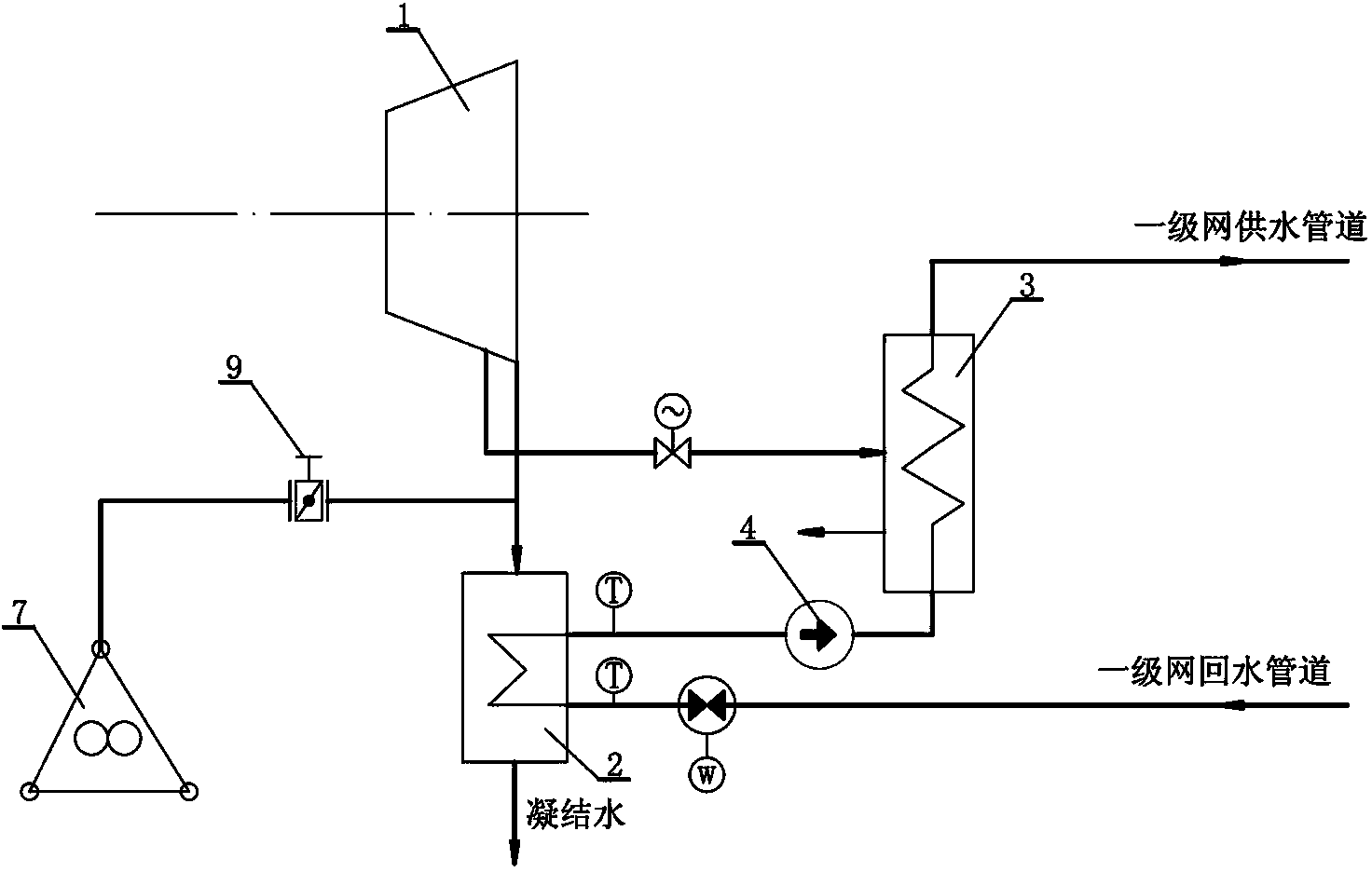
[0027] Such as figure 2 As shown, the uncondensed exhaust steam of the condenser 2 is cooled by the air cooling island 7 of the power plant connected to the exhaust steam regulating valve 9 . That is, a proper amount of exhaust steam from the exhaust port of the steam turbine 1 of the power plant enters the condenser 2, and conducts preliminary heat exchange through the hot water heat exchange channel for the return water pipe of the primary network, and the remaining exhaust steam passes through the air cooling island of the power plant connected by the exhaust steam regulating valve 9 7 Cool. All the other structures are the same as in Embodiment 1.

[0028] This structure is suitable for power plants with an air-cooling system lacking in water sources, and part of the exhaust steam that is not utilized by the hot water heat exchange channel is cooled by the air-cooling island 7 .

[0029] Utilize the energy-saving d...


PUM


Abstract

The invention relates to an energy saving device for using waste heat of a power plant for urban centralized heat supply and an energy saving method of the energy saving device. According to the structure of the energy saving device, a steam exhaust opening of a power plant turbine is cooled through a power plant cooling system, a heat supply main heat exchanger is arranged on a heat supply primary network, and a heat source inlet of the heat supply main heat exchanger is connected with a steam extraction opening of the power plant turbine; the steam exhaust opening of the power plant turbine is connected with an inlet of a condenser; a hot water heat exchange channel is formed in the condenser, a primary network water return pipeline is connected with an inlet of the hot water heat exchange channel, and an outlet of the hot water heat exchange channel is connected with an inlet of the heat supply main heat exchanger through a heat supply main circulating pump; uncondensed waste steam of the condenser is cooled through the power plant cooling system. The energy saving device enables a steam condensing system of the power plant and an urban concentrated heat supply system to be combined in a high degree, a steam condensing device of the power plant is transformed, system waste heat which is originally exhausted to the atmosphere is recycled as much as possible, in this way, the comprehensive heat efficiency of the power plant is improved, power generation energy consumption is lowered, and part of the heat source problem of urban heat supply is solved.

Description

technical field [0001] The invention relates to an energy-saving device and an energy-saving method for directly recovering waste heat from a condenser of a power plant for heat supply, and relates to two directions of combined heat and power generation and urban central heating. Background technique [0002] Since the 1960s, my country has adopted the combined heat and power central heating mode to provide heating to urban buildings. The adoption of combined heat and power technology has played an important role in improving energy efficiency, improving urban environmental quality, and facilitating life. [0003] Combined heat and power generation is a successful example of cascade utilization of thermal energy. It uses high-level thermal energy for power generation and relatively low-level thermal energy for heating. The energy utilization rate of pure condensing power plants is below 40%. The energy utilization rate of cogeneration can reach 60%. However, more than 30% ...

Claims


Application Information

Patent Timeline
IPC IPC(8): F24D3/10F24D3/02
Inventor 刘枫黄寿山
Owner SHENYANG MAPLE ENERGY TECH
Why Eureka
Try Eureka