
Catalytic membrane contactor and gas desulfurization and denitrification method

A technology of desulfurization and denitrification, membrane contactor, applied in chemical instruments and methods, separation methods, separation of dispersed particles, etc., can solve the problems of poor removal rate and low absorption efficiency, achieve wide application range and improve mass transfer efficiency And, the effect of increasing the degree of turbulence

Active Publication Date: 2021-10-01
NANJING TECH UNIV
View PDF10 Cites 0 Cited by
  • Summary
  • Abstract
  • Description
  • Claims
  • Application Information

AI Technical Summary

Problems solved by technology

The method of this patent mainly uses sodium hydroxide solution as the absorbent to absorb the exhaust gas. However, this method will need to remove nitrogen oxides and sulfur oxides through membrane absorption at the same time, which will easily lead to The problem of low absorption efficiency and poor removal rate

Method used


Image

  • Catalytic membrane contactor and gas desulfurization and denitrification method
  • Catalytic membrane contactor and gas desulfurization and denitrification method
  • Catalytic membrane contactor and gas desulfurization and denitrification method

Examples


Embodiment 1

[0064] The catalytic membrane contactor is installed at the exhaust outlet of the ship, after the particulate filter. The absorbent is injected into the liquid inlet area from the liquid inlet head, and the absorbent flows out from the liquid outlet head through the ceramic membrane tube, and then enters the absorption liquid cooler and then circulates into the catalytic membrane contactor. After adding 500ppm ammonia to the tail gas, it enters the gas phase area of ​​the catalytic membrane contactor through the gas inlet (the gas temperature is about 200°C and the liquid temperature is about 95°C). The temperature is about 60°C) and discharged. The NaOH solution with a concentration of 0.1mol / L is used as the absorption liquid, and the flow rate is 100m 3 / h. Exhaust gas flow is 50m 3 / h, where SO 2 The concentration is 100ppm, and the NO concentration is 100ppm. The volume of catalytic membrane contactor equipment is 4.5m 3 , the pore diameter of the membrane tube is 0...

Embodiment 2

[0066] The catalytic membrane contactor is installed at the exhaust outlet of the ship, after the particulate filter. The absorbent is injected into the liquid inlet area from the liquid inlet head, and the absorbent flows out from the liquid outlet head through the ceramic membrane tube, and then enters the absorption liquid cooler and then circulates into the catalytic membrane contactor. After adding 800ppm ammonia to the tail gas, it enters the gas phase area of ​​the catalytic membrane contactor through the gas inlet (the gas temperature is about 150°C and the liquid temperature is about 90°C). The temperature is about 50°C) and discharged. The NaOH solution with a concentration of 1mol / L is used as the absorption liquid, and the flow rate is 300m 3 / h. Exhaust gas flow is 300m 3 / h, where SO 2 The concentration is 1000ppm, and the NO concentration is 1000ppm. The volume of catalytic membrane contactor equipment is 78.6m 3 , the pore diameter of the membrane tube is...

Embodiment 3

[0068] The catalytic membrane contactor is installed at the exhaust outlet of the ship, after the particulate filter. The absorbent is injected into the liquid inlet area from the liquid inlet head, and the absorbent flows out from the liquid outlet head through the ceramic membrane tube, and then enters the absorption liquid cooler and then circulates into the catalytic membrane contactor. After adding 800ppm ammonia gas to the tail gas, it enters the gas phase area of ​​the catalytic membrane contactor through the gas inlet (gas temperature is about 180°C and liquid temperature is about 90°C), and is reacted by the catalyst through the gas outlet (gas temperature is about 120°C and liquid temperature is about 120°C). The temperature is about 70°C) and discharged. Ca(OH) with a concentration of 0.5mol / L 2 The solution is used as the absorption liquid, the flow rate is 100m 3 / h. Exhaust gas flow is 200m 3 / h, where SO 2 The concentration is 100ppm, and the NO concentrati...


PUM


Abstract

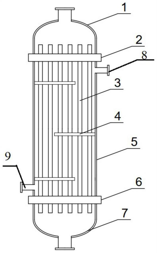
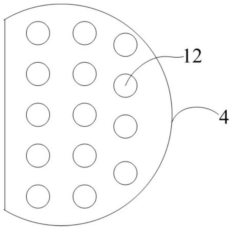
The invention relates to a catalytic membrane contactor for desulfurization and denitrification of ship tail gas, and the simultaneous desulfurization and denitrification process is realized by using the membrane contactor for tail gas containing sulfur and nitrate. The membrane contactor consists of a cylinder, ceramic membrane tubes and catalyst plates. The upper and lower ends of the barrel are respectively provided with a gas feed port and a gas discharge port, and a denitrification catalyst is loaded on the catalyst plate. The desulfurization and denitrification coupling process uses the above-mentioned membrane contactor. The absorbent is injected from the liquid inlet head, flows out from the liquid outlet head through the ceramic membrane tube, and then enters the absorption liquid cooler and then circulates into the catalytic membrane contactor. The tail gas enters the catalytic membrane contactor through the gas inlet, and is discharged from the gas outlet after reacting in the contactor. In this process, the absorbent is mainly used for desulfurization and solving the problem of ammonia escape, and the supported catalyst is mainly used for catalytic denitrification. The method couples the SCR technology with the membrane absorption technology, and has the advantages of high integration, strong controllability, high removal efficiency, compact structure and easy enlargement, and improved desulfurization and denitrification efficiency.

Description

technical field [0001] The invention relates to a catalytic membrane contactor used for desulfurization and denitrification of ship tail gas, in particular to a simultaneous desulfurization and denitrification process using the catalytic membrane contactor for tail gas containing sulfur and nitrate. Background technique [0002] Nitrogen oxides (NO, NO 2 , N 2 O etc., referred to as NO x ) is one of the main air pollutants. In recent years, the country has paid more and more attention to the problem of environmental pollution, such as NO from mobile sources such as ships x Emission standards are also getting stricter. During the operation of the diesel engine, NO x The main reason is that nitrogen reacts with oxygen in the air under high temperature and pressure, so it is impossible to eliminate NO from the source x generation. The tail gas must be denitrified, and selective catalytic reduction (SCR) is the treatment of NO x effective method. [0003] According to th...

Claims


Application Information

Patent Timeline
Patent Type & Authority Patents(China)
IPC IPC(8): B01D53/86B01D53/50B01D53/56B01D53/78B01D53/90
CPCB01D53/502B01D53/504B01D53/56B01D53/8631B01D53/90
Inventor 邱鸣慧孔祥力符开云徐鹏陈献富范益群
Owner NANJING TECH UNIV
Learn More