Temperature-retaining fresh air ventilator

A technology of fresh air ventilators and fresh air passages, which is applied in ventilation systems, shielding with air flow, space heating and ventilation, etc. The complex structure of the machine can improve the heat exchange efficiency, the structure is simple and reasonable, and the weight is reduced.

Active Publication Date: 2014-08-06
SHENZHEN ZPWTECHNOLOGY CO LTD
View PDF6 Cites 4 Cited by
  • Summary
  • Abstract
  • Description
  • Claims
  • Application Information

AI Technical Summary

Problems solved by technology

However, the structure of the fresh air ventilator is complex, and the heat exchange method is a cross-flow type, and in terms of the size of the entire ventilator, the size of the heat exchange core only accounts for about one-fifth of the total size, resulting in the size of the ventilator. The overall structure is large in size, heavy in weight and low in heat transfer efficiency
The energy recovery efficiency of the device is difficult to achieve the 80% stated in the patent document
[0006] At present, the honeycomb heat exchanger in China is a honeycomb ceramic structure, which is used for the recovery of high-temperature flue gas waste heat. The thickness of the hole wall is thick, the thermal resistance is large, and the heat exchange efficiency is low. At the same time, the manufacturing process is complicated, the cost is high, and the volume is large. heavy weight

Method used


Image

  • Temperature-retaining fresh air ventilator
  • Temperature-retaining fresh air ventilator
  • Temperature-retaining fresh air ventilator

Examples


Embodiment Construction

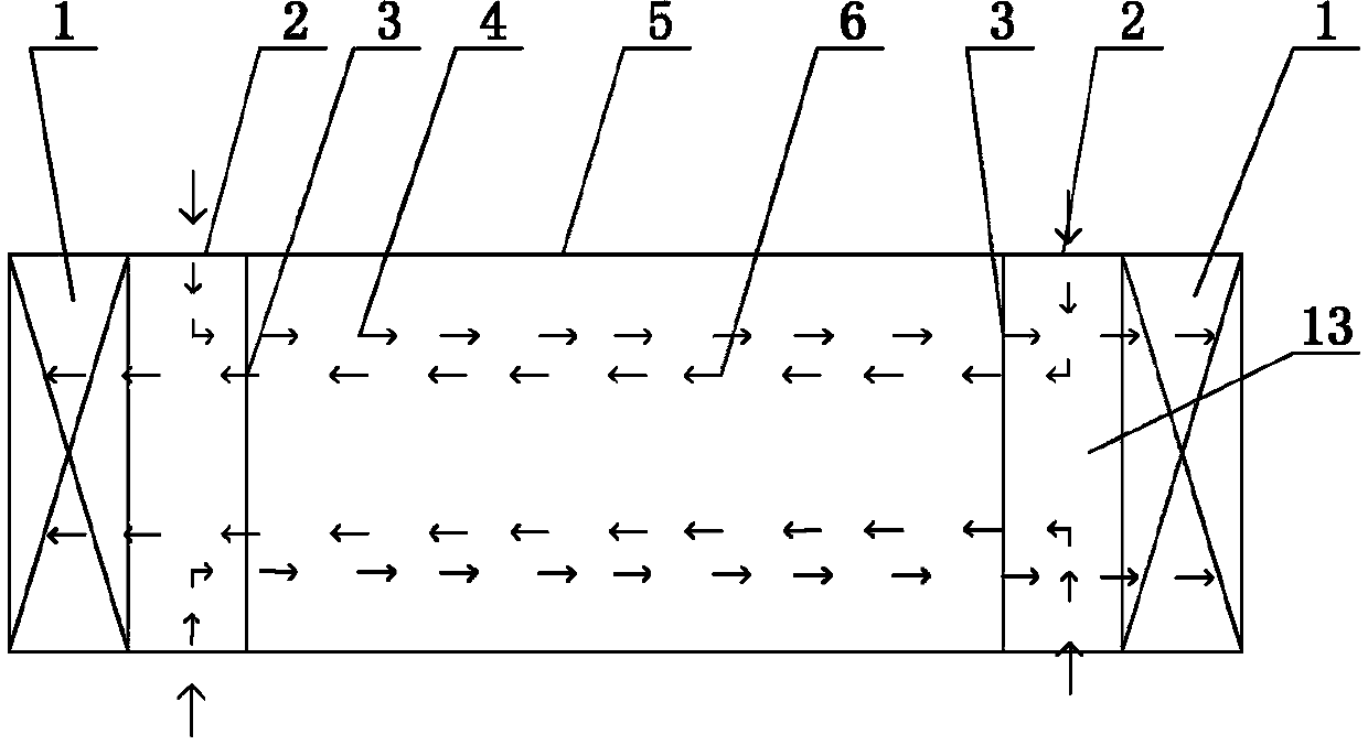
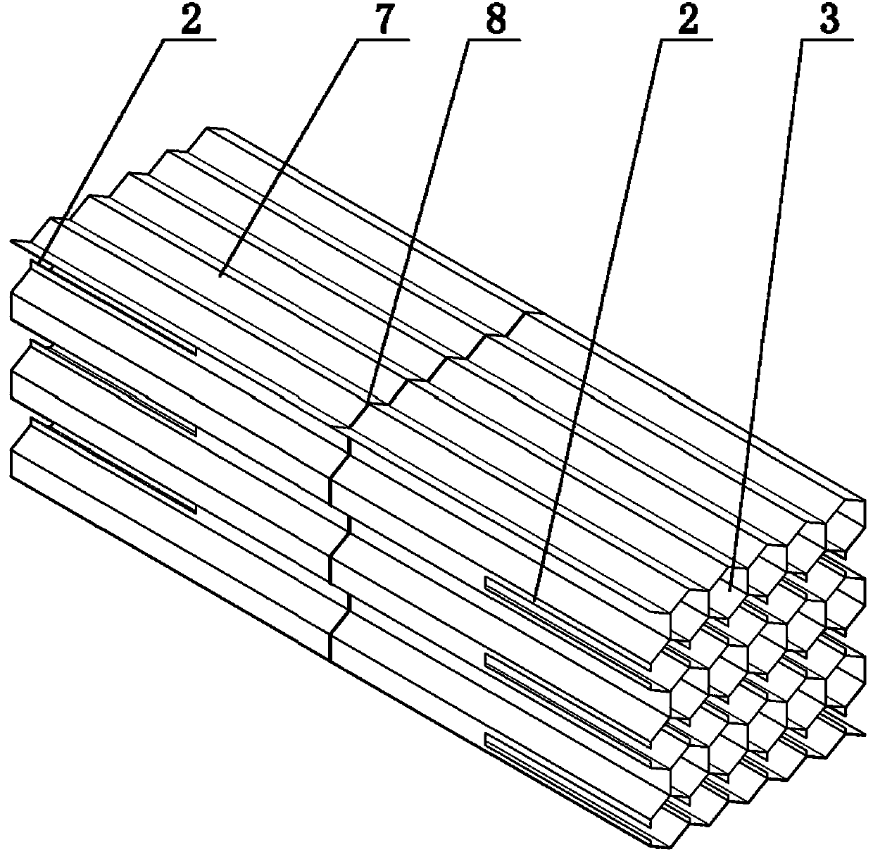
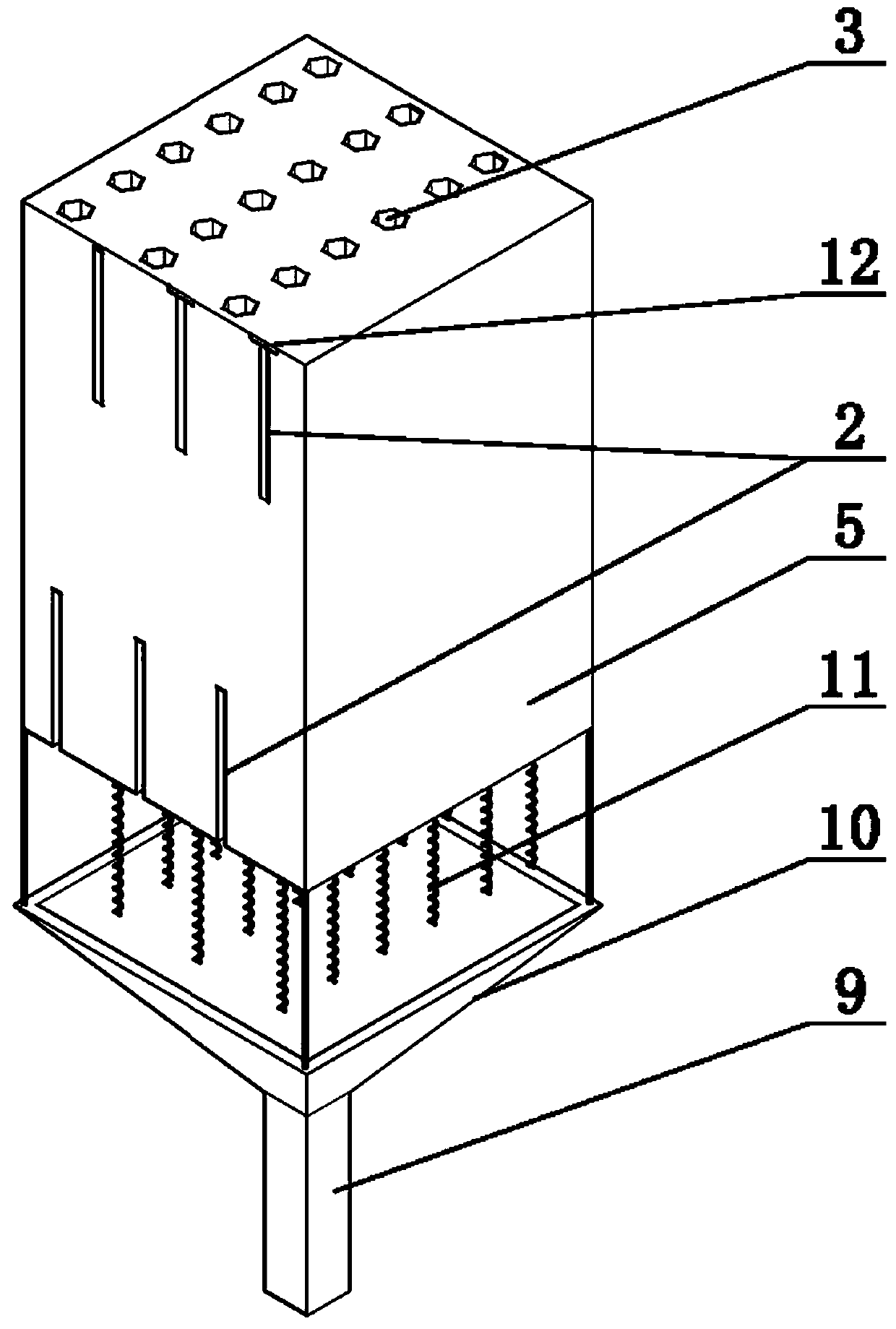
[0025] The present invention includes a housing 5 in which a once-formed honeycomb body 7 is provided. The honeycomb body 7 is provided with a fresh air passage 4 and an exhaust air passage 6 at intervals; the air intake of the fresh air passage 4 and the exhaust air passage 6 The openings 2 are respectively arranged on the side surfaces of the two ends of the honeycomb body 7, and the air outlets 3 of the fresh air channel 4 and the exhaust channel 6 are respectively arranged on the end faces of the two ends of the honeycomb body 7.

[0026] As a preferred solution of the present invention, both ends of the casing 5 are provided with a flow guiding device 1 corresponding to the air outlets 3 of the fresh air channel 4 and the exhaust air channel 6.

[0027] The guiding device 1 may be a fan.

[0028] Further, the honeycomb body 7 is arranged vertically, and the air guiding device 1 of the air outlet 3 of the air exhaust channel 6 is arranged as a chimney. A chimney is arranged at t...


PUM


Abstract

The invention relates to a temperature-retaining fresh air ventilator, and relates to an improvement on a fresh air ventilator structure. The temperature-retaining fresh air ventilator is low in production cost, simple in manufacturing technology and high in heat exchange efficiency. The temperature-retaining fresh air ventilator comprises a housing, and has the structural features that a honeycomb integrally molded is arranged in the housing; fresh air channels and exhaust air channels are arranged in the honeycomb at intervals; air inlets of the fresh air channels and the exhaust air channels are respectively formed in sides at two ends of the honeycomb; air outlets of the fresh air channels and the exhaust air channels are respectively formed in end faces at the two ends of the honeycomb.

Description

Technical field [0001] The invention relates to an improvement in the structure of a fresh air ventilator. Background technique [0002] At present, most of the fresh air ventilators appearing on the market adopt a plate-fin cross-flow heat exchange core with a corrugated plate support structure. The corrugated plate support can solve the support problem of the heat exchange plate, but the resistance pressure drop will follow. Increased, cross-flow heat exchange efficiency is not as good as counter flow; in addition, the volume of the fresh air ventilator is directly limited by the diagonal length of the core, so this type of heat exchange core has low heat exchange efficiency, large volume, high cost, and manufacturing Problems such as inconvenience and large resistance pressure drop. [0003] Most counter-flow heat exchanger cores use corrugated plates to overlap each other to form a cavity. The processing technology is complicated. The volume or thickness of the cavity cannot b...

Claims


Application Information

Patent Timeline
Patent Type & Authority Applications(China)
IPC IPC(8): F24F7/08F24F12/00F24F13/30
Inventor 张岩
Owner SHENZHEN ZPWTECHNOLOGY CO LTD
Why Eureka
Try Eureka