Smart ultrasonic physical therapy instrument
A physical therapy instrument and ultrasonic technology, applied in the field of intelligent ultrasonic physical therapy instrument, can solve the problems of single treatment frequency, low efficiency, complicated operation, etc., and achieve the effect of improving treatment effect, convenient use, and improving equipment efficiency
- Summary
- Abstract
- Description
- Claims
- Application Information
AI Technical Summary
Problems solved by technology
Method used
Image
Examples
Embodiment 1
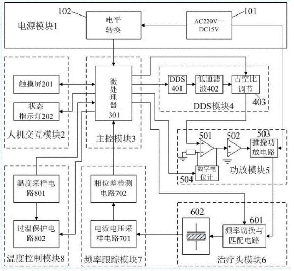
[0042] see figure 1 As shown, an intelligent dual-frequency ultrasonic physiotherapy instrument includes a power supply module 1, a human-computer interaction module 2, a main control module 3, a DDS module 4, a power amplifier module 5, a treatment head module 6, a frequency tracking module 7 and a temperature control module 8 ;
[0043] The power supply module 1 includes a 220V AC to DC 15V power supply module 101, and the 220V AC to DC 15V power supply module 101 is connected with a level conversion module 102; the 220V AC to DC 15V power supply module 101 converts AC 220V to DC 15V To provide power to the push-pull power amplifier circuit 503; the level conversion module 102 converts the DC 15V voltage into various voltages required by the main control module 3 and the human-computer interaction module 2.
[0044] The human-computer interaction module 2 includes a touch screen 201 and a status display light 202; through the touch screen 201, various treatment parameters ...
Embodiment 2
[0058] See attached figure 2 , The microprocessor controls the DDS integrated chip to generate ultrasonic excitation signals. The DDS integrated chip adopts AD9851 of AD Company, and the output frequency is up to 180MHz. It can generate output signals such as sine wave, square wave and triangle wave, etc., with low power consumption. The microprocessor is connected through the serial bus, and the 50MHz active crystal oscillator is used as the reference clock. The output sine wave excitation signal passes through the low-pass filter circuit composed of R, L, and C; the signal after filtering out the harmonic interference enters the duty ratio adjustment Circuit; the duty ratio adjustment circuit is composed of high-speed analog switches, and the microprocessor realizes the control of the duty ratio of the excitation signal by adjusting the duty ratio of the input B-terminal signal: when the B-terminal is high, fout=fin; when the B-terminal is low Usually, fout=GND(0V), within ...
Embodiment 3
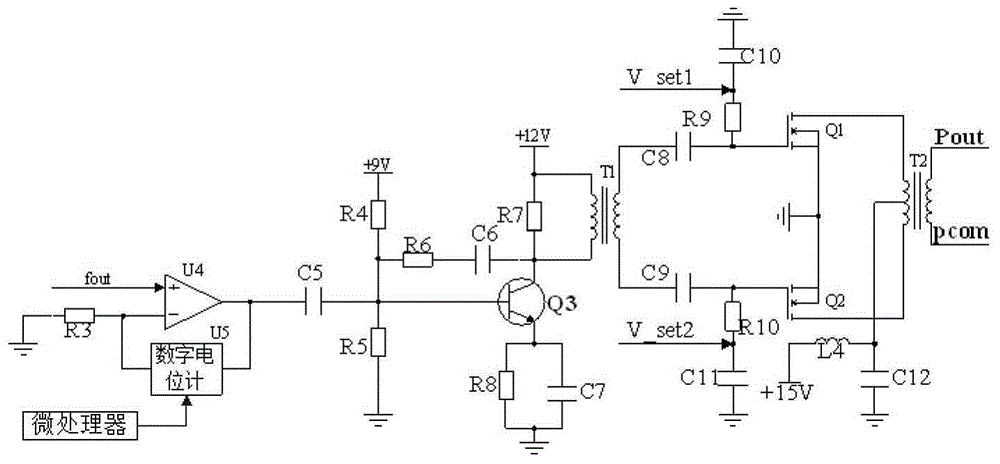
[0060] See attached image 3 , in the power amplifier module, U4 forms a first-stage amplifier circuit, and the excitation signal is input from the same-phase terminal to form the same-phase proportional amplifier circuit. The amplification factor is determined by the ratio of the output resistance of the digital potentiometer to R3. The size of the resistance value, so as to control the size of the output voltage, and further realize the control of the output power; the output power of U4 is about 1W; C5 is a coupling capacitor; Q3 constitutes a secondary amplifier circuit, and R4 and R5 constitute a bias after voltage division circuit, R6 and C6 are used for feedback compensation. After Q3 is amplified, the output power reaches about 5W, which is coupled to the push-pull power amplifier circuit through transformer T1; V_set1 and V_set2 are used to set the quiescent working current of Q1 and Q2. Adjustment, Q1 and Q2 are power MOS tubes, T2 is an output transformer, and L4 is...
PUM
 Abstract
Description
Claims
Application Information
 - R&D
- Intellectual Property
- Life Sciences
- Materials
- Tech Scout
- Unparalleled Data Quality
- Higher Quality Content
- 60% Fewer Hallucinations
Browse by: Latest US Patents, China's latest patents, Technical Efficacy Thesaurus, Application Domain, Technology Topic, Popular Technical Reports.
© 2025 PatSnap. All rights reserved.Legal|Privacy policy|Modern Slavery Act Transparency Statement|Sitemap|About US| Contact US: help@patsnap.com


