Accurate positioning device for engine cylinder block sand core

An engine cylinder block and precise positioning technology, applied in the direction of cores, molding machine parts, casting molding equipment, etc., can solve the problems of easy to change the position of the sand core, easy to change the position of the sand core, easy to damage the sand core, etc., to achieve improved The effect of product quality, ease of promotion and use, and low manufacturing cost

Active Publication Date: 2014-08-13
上柴动力海安有限公司
View PDF5 Cites 3 Cited by
  • Summary
  • Abstract
  • Description
  • Claims
  • Application Information

AI Technical Summary

Problems solved by technology

However, because, 1, the core assembly process for the top cover core and the bottom cover core must be manually participated, and it is easy to change the position of the sand core; 2, when the sand core is dried in the surface drying furnace, the thermal expansion coefficient of the sand core and the ordinary positioning pin are different, here Too tight fit between positioning pin and sand core process hole will easily damage the sand core, and too loose fit will easily change the position of the sand core during transportation in the surface drying furnace; 3. The final molding process requires the cylinder head top cover core and cylinder head bottom cover The position of the core is strictly corresponding, otherwise the sand core will be damaged. There are several difficulties above, so the automatic production of cylinder head sand core has not been realized before.

Method used


Image

  • Accurate positioning device for engine cylinder block sand core
  • Accurate positioning device for engine cylinder block sand core
  • Accurate positioning device for engine cylinder block sand core

Examples


Embodiment Construction

[0015] The present invention will be described in further detail below in conjunction with the accompanying drawings.

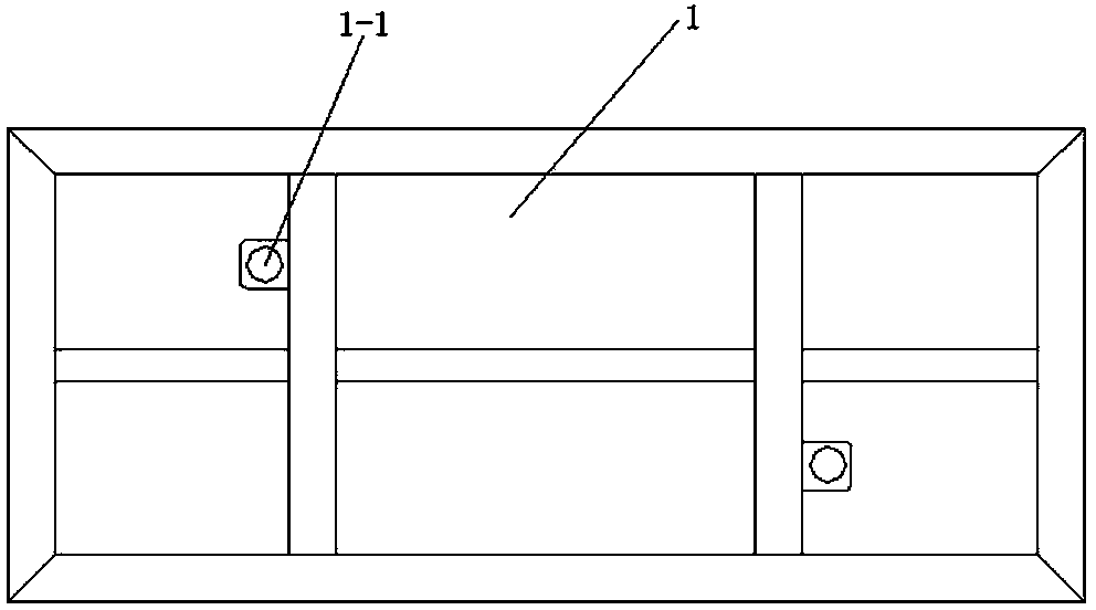
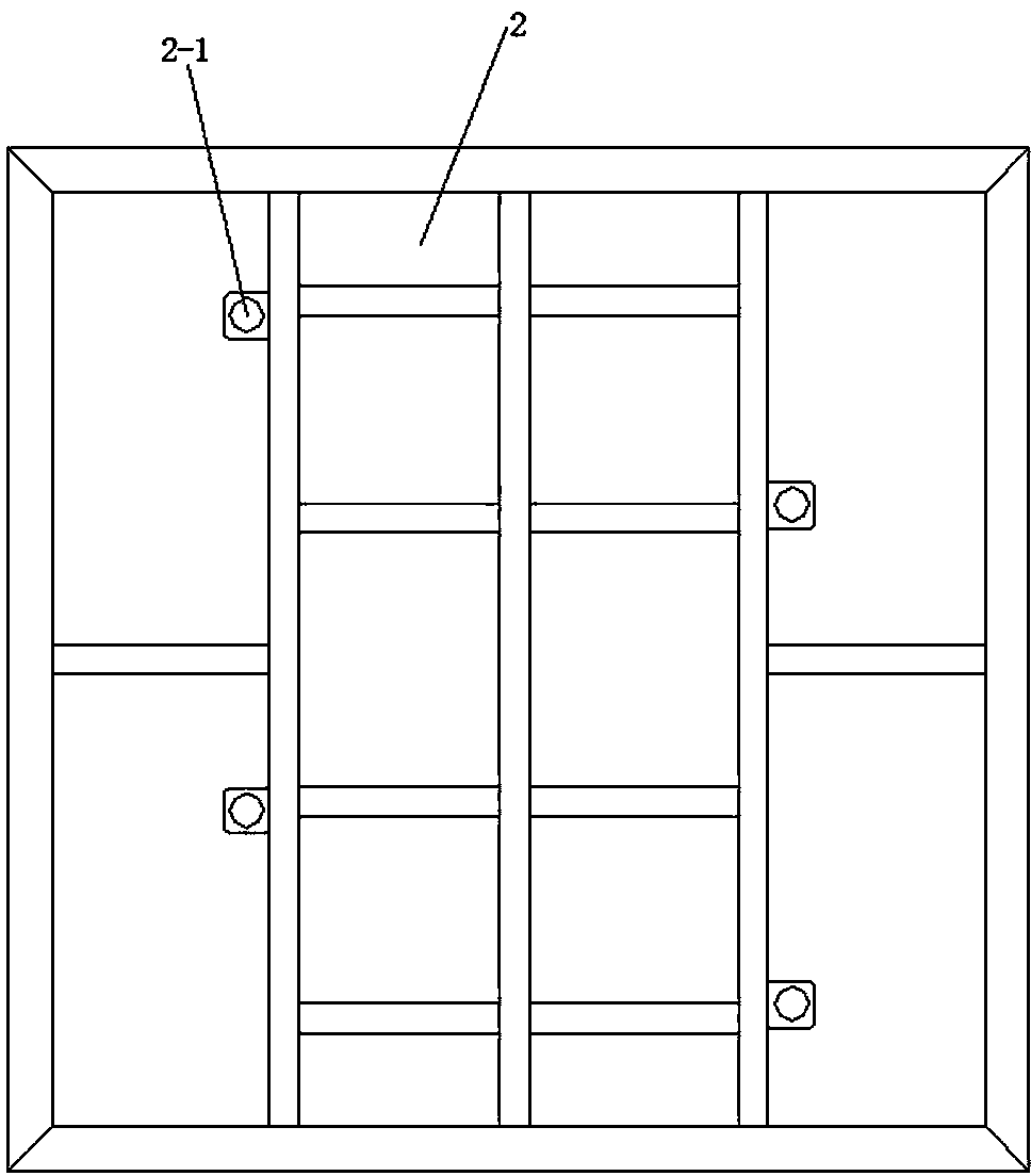
[0016] Such as figure 1 , figure 2 , image 3 , Figure 4 , Figure 5 As shown, the precise positioning device for the engine cylinder sand core includes a primary positioning support plate 1, a secondary positioning support plate 2 and a positioning jacking mechanism.

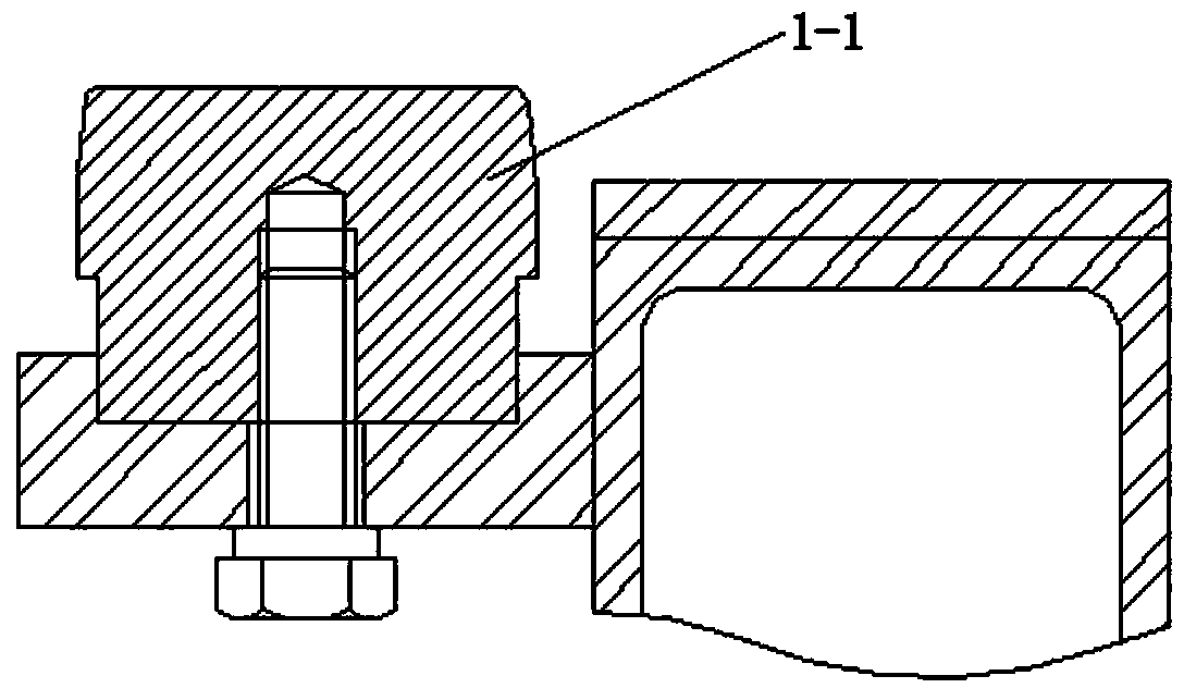
[0017] Among them, such as figure 1 , image 3 As shown, the primary positioning pallet 1 is a steel welding pallet, and two first positioning pin shafts 1-1 are arranged at diagonal positions on the primary positioning pallet 1, and the two first positioning pin shafts 1 -1 is fixedly connected with the primary positioning support plate 1 by bolts, and the two first positioning pin shafts 1-1 are respectively matched with the process holes of the cylinder head top cover core and the cylinder head bottom cover core, and the clearance fit is δ≤ 1mm. In this embodiment, the primary pos...


PUM


Abstract

The invention relates to the technical field of positioning devices, and in particular relates to an accurate positioning device for an engine cylinder block sand core. The accurate positioning device comprises a primary positioning support plate, a secondary positioning support plate and a positioning climbing mechanism. Firstly the primary positioning support plate is adopted for primary positioning for a cylinder cover top cover core and a cylinder cover bottom cover core, then the secondary positioning support plate is adopted for secondary positioning for the cylinder cover top cover core and the cylinder cover bottom cover core, and finally the positioning climbing mechanism is adopted for accurate positioning during mould assembling. The positioning climbing mechanism can be lifted automatically according to set production takt, two positioning elongated conical pins at the top of the positioning climbing mechanism can penetrate through a neutral gear of the secondary positioning support plate when being lifted along with a climbing machine, and primary positioning for other two technical holes (deeper) of a cylinder cover sand core is realized. In the positioning device, since the position of the climbing mechanism is unchanged all the time, the position of the sand core climbed every time is unique, and the grabbing precision and mould assembling precision of a robot can be fully met.

Description

technical field [0001] The invention relates to the technical field of positioning devices, in particular to a precise positioning device for engine cylinder sand cores. Background technique [0002] Casting is the earliest thermal processing technology mastered by human beings. Casting is a process in which metals are smelted into liquids that meet certain requirements and poured into molds. After cooling, solidification, and cleaning, castings with predetermined shapes, sizes, and properties are obtained. Because the casting blank is almost formed, the purpose of free machining or a small amount of machining reduces the cost and reduces the production time to a certain extent. Casting is one of the basic processes of modern device manufacturing industry. In the modern foundry industry, because the molding materials used in sand casting are cheap and easy to obtain, and the casting mold is easy to manufacture, it can be adapted to single-piece production, batch production ...

Claims


Application Information

Patent Timeline
Patent Type & Authority Applications(China)
IPC IPC(8): B22C19/00B22C9/10
Inventor 姜金文
Owner 上柴动力海安有限公司
Why Eureka
Try Eureka