LaNiO3 thin film-forming composition and method of forming LaNiO3 thin film using the same
一种组合物、薄膜的技术,应用在镍化合物、化学仪器和方法、氧化物导体等方向,能够解决膜电阻率增大等问题,达到提高保存稳定性的效果
- Summary
- Abstract
- Description
- Claims
- Application Information
AI Technical Summary
Problems solved by technology
Method used
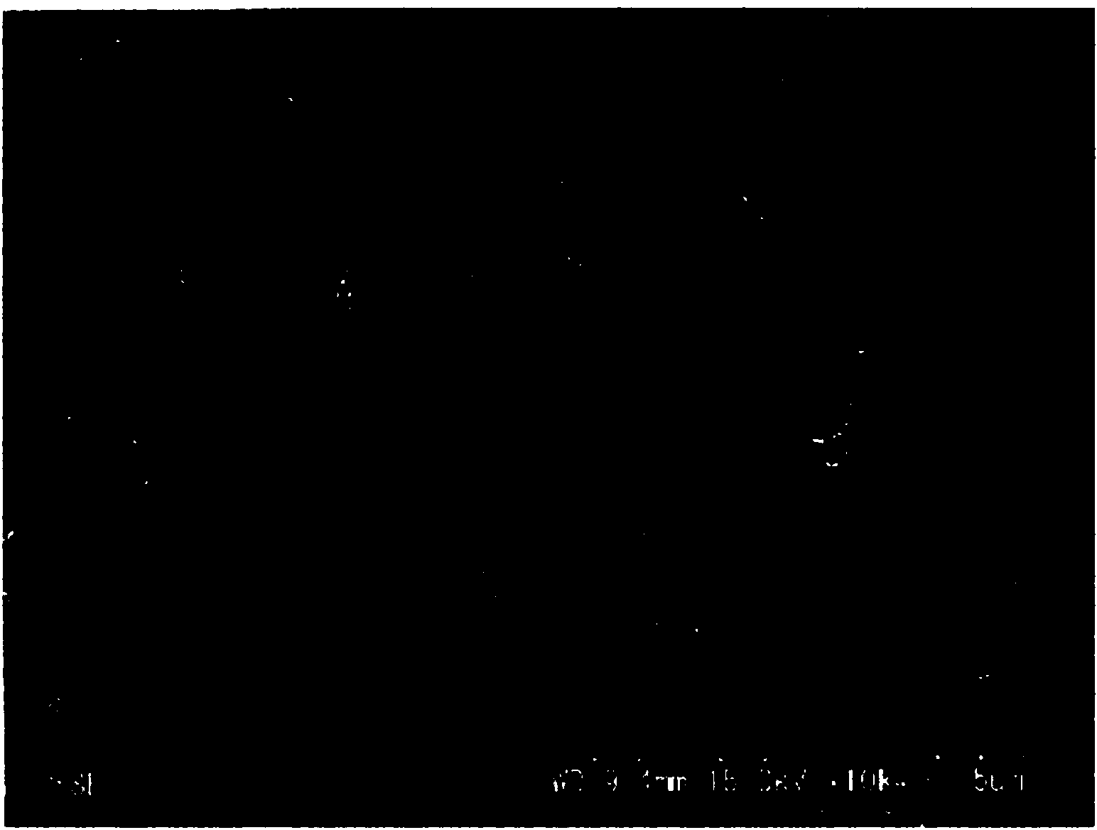
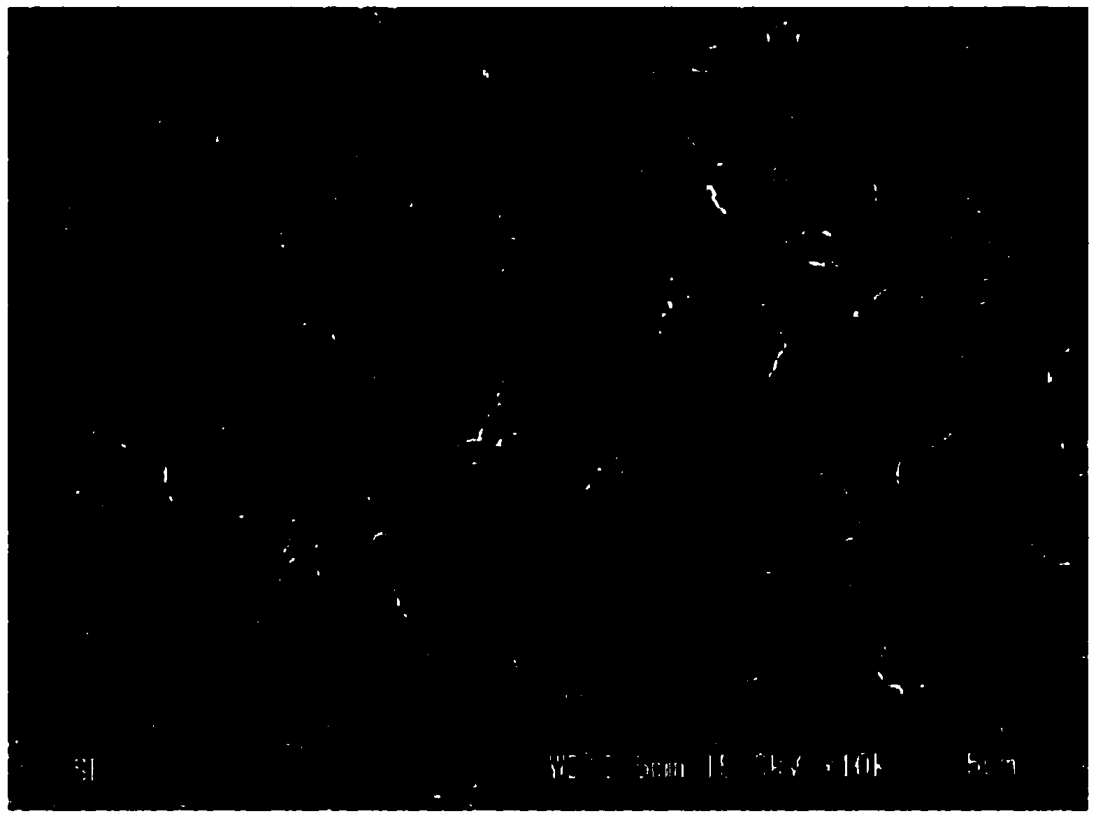
Image

Examples
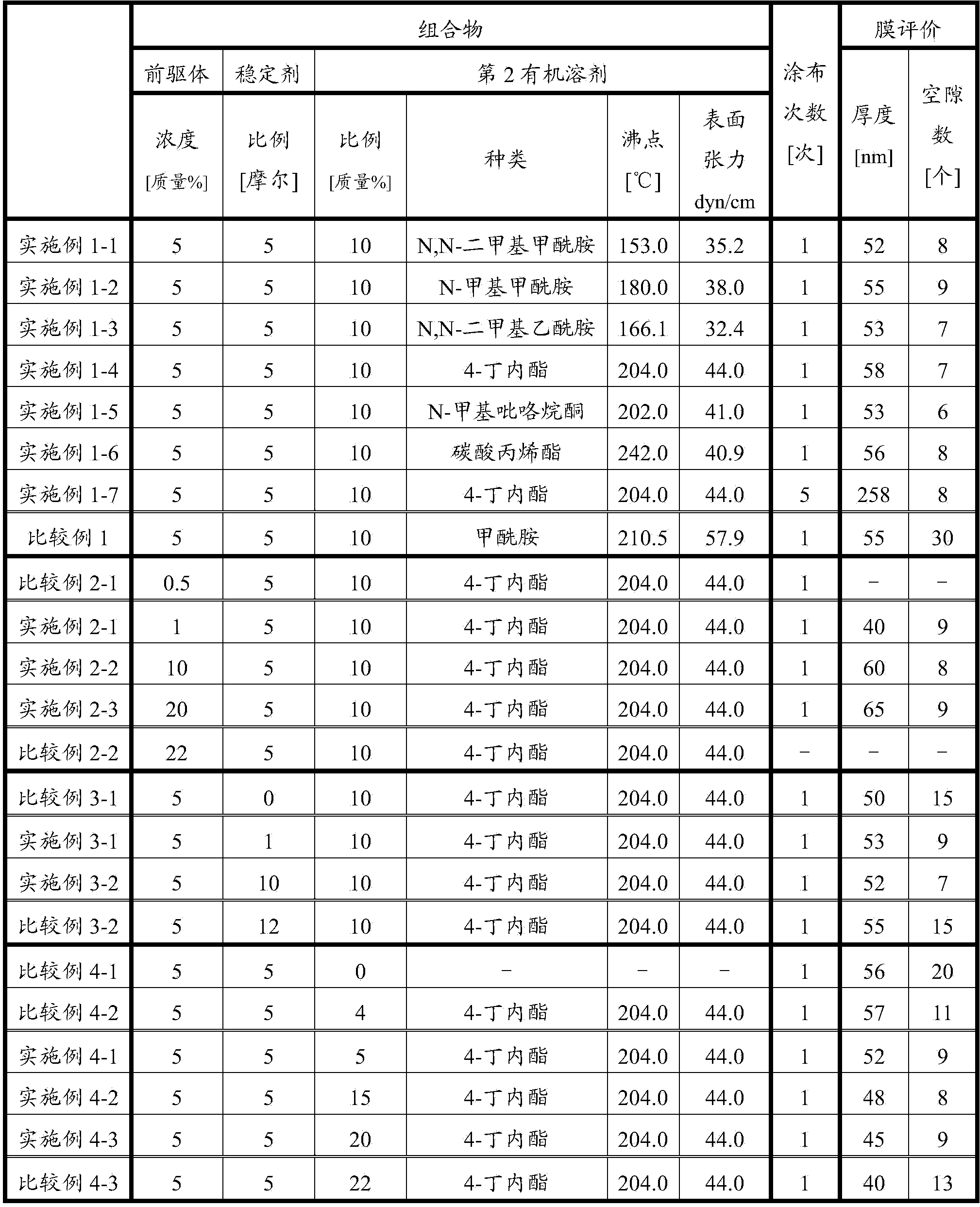
Embodiment 1
[0045]
[0046] The composition was prepared in the same manner as in Example 1-1, and LaNiO 3 film.
Embodiment 1-7
[0048] The composition was prepared in the same manner as in Example 1-4, and LaNiO 3 film.
Embodiment 2-1~2-3
[0049]
[0050] As shown in Table 1 below, except that the ratio of each component is adjusted to change the concentration of the precursor in terms of oxides in the composition, the composition is prepared in the same way as in Examples 1-4 and LaNiO is formed. 3 film.
PUM
| Property | Measurement | Unit |
|---|---|---|
| boiling point | aaaaa | aaaaa |
| surface tension | aaaaa | aaaaa |
| boiling point | aaaaa | aaaaa |
Abstract
Description
Claims
Application Information
 - R&D
- Intellectual Property
- Life Sciences
- Materials
- Tech Scout
- Unparalleled Data Quality
- Higher Quality Content
- 60% Fewer Hallucinations
Browse by: Latest US Patents, China's latest patents, Technical Efficacy Thesaurus, Application Domain, Technology Topic, Popular Technical Reports.
© 2025 PatSnap. All rights reserved.Legal|Privacy policy|Modern Slavery Act Transparency Statement|Sitemap|About US| Contact US: help@patsnap.com