Dynamic pressurized tempering furnace for tempering saw blade matrix and tempering process

A technology of tempering furnace and substrate, applied in furnaces, heat treatment furnaces, manufacturing tools, etc., can solve the problems of uneven metallographic structure of saw blade substrate, shorten the service life of saw blade, reduce the service life of saw blade, etc., and save energy consumption. , The effect of protecting production equipment and prolonging service life

Inactive Publication Date: 2014-08-13
成都壹佰科技有限公司
View PDF6 Cites 12 Cited by
  • Summary
  • Abstract
  • Description
  • Claims
  • Application Information

AI Technical Summary

Problems solved by technology

The saw blade matrix is ​​stacked in the tempering furnace for heat treatment. The existing tempering furnace achieves uniform heating in the furnace body through the combination of furnace cover, inner tank and air circulation heating device, thus realizing the saw blade matrix in the furnace body. After heating, the metallographic structure of the saw blade matrix obtained after tempering is uneven, the internal residual stress is large, and the average value of the flatness of the saw blade is 0.05mm, which reduces the service life of the saw blade
There is also a box-type tempering furnace. Through the combination of temperature controller and thermocouple, the tempering of the saw blade substrate is realized. The average flatness of the saw blade after tempering is 0.04mm, which seriously affects the quality of the saw blade. Reduced service life of saw blades

Method used


Image

  • Dynamic pressurized tempering furnace for tempering saw blade matrix and tempering process
  • Dynamic pressurized tempering furnace for tempering saw blade matrix and tempering process
  • Dynamic pressurized tempering furnace for tempering saw blade matrix and tempering process

Examples


Embodiment Construction

[0020] The present invention will be further described below in conjunction with accompanying drawing, protection scope of the present invention is not limited to the following:

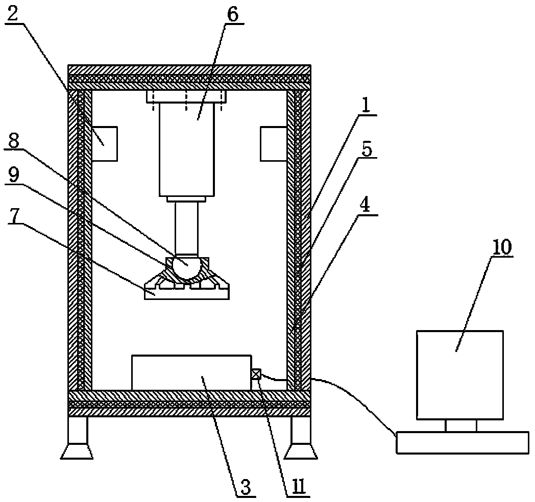
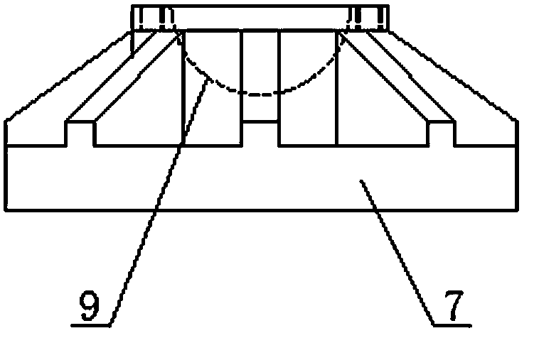
[0021] Such as figure 1 As shown, a dynamic pressure tempering furnace for tempering the saw blade substrate includes a furnace body 1, a heating device 2 and a bearing platform 3, the heating device 2 and the bearing platform 3 are all arranged in the furnace body 1, and the furnace body 1 is provided with a fire-proof layer 4 on the inner wall, and an insulation layer 5 is provided between the fire-proof layer 4 and the furnace body 1. The insulation layer 5 prevents heat exchange between the temperature in the furnace body 1 and the outside air, and saves the energy of the heating device 2. consume. Such as figure 1 As shown, it also includes an oil cylinder 6 and a pressure head 7, the oil cylinder 6 is perpendicular to the top of the furnace body 1 and is arranged in the furnace body 1, and th...


PUM

PropertyMeasurementUnit
radiusaaaaaaaaaa

Abstract

The invention discloses a dynamic pressurized tempering furnace for tempering a saw blade matrix. The dynamic pressurized tempering furnace comprises a furnace body (1), a heating device (2) and a bearing platform (3), wherein the heating device (2) and the bearing platform (3) are both arranged in the furnace body (1); the inner wall of the furnace body (1) is provided with a fire protection layer (4); an oil cylinder (6) is vertical to the top of the furnace body (1) and is arranged in the furnace body (1); the bottom of a piston rod of the oil cylinder (6) is provided with a spherical boss (8); a pressure head (7) is internally provided with a spherical groove (9). The dynamic pressurized tempering furnace also comprises a controller, a display (10) and a temperature sensor (11), wherein the controller is connected with the oil cylinder (6) and the heating device (2). The dynamic pressurized tempering furnace is compact in structure, capable of automatically regulating the angle of the pressure head according to the planeness of a saw blade and convenient for workers to operate. After being subjected to thermal treatment by the dynamic pressurized tempering furnace, the saw blade matrix is uniform in crystalline phase tissue, small in internal residual stress and low in saw blade planeness less than 0.03mm.

Description

technical field [0001] The invention relates to the technical field of heat treatment of a woodworking circular saw blade base body, in particular to a dynamic pressure tempering furnace for tempering the saw blade base body and a tempering process for the saw blade base body. Background technique [0002] Woodworking saw blades are mostly in the shape of discs and are used for processing wood. The saw blade base is a semi-finished product obtained through a series of machining processes. The strength and toughness of the saw blade base are very low. Therefore, the saw blade base needs to be tempered to obtain a high-strength saw blade. The saw blade matrix is ​​stacked in the tempering furnace for heat treatment. The existing tempering furnace achieves uniform heating in the furnace body through the combination of furnace cover, inner tank and air circulation heating device, thus realizing the saw blade matrix in the furnace body. After heating, the metallographic structur...

Claims


Application Information

Patent Timeline
Patent Type & Authority Applications(China)
IPC IPC(8): C21D9/24C21D1/26C21D11/00
Inventor 李小娟蒋勇
Owner 成都壹佰科技有限公司
Why Eureka
Try Eureka