Composite damping device for vibration and noise reduction of gear shafting

A technology of vibration reduction, noise reduction, and damping device, which is applied in the direction of gear vibration/noise attenuation, transmission parts, belts/chains/gears, etc., and can solve the problem that the gear shaft does not have effective vibration reduction, broadband vibration reduction cannot be achieved, and the scope of application Limited and other problems, to achieve obvious vibration reduction effect, flexible installation space, and strong stability

Active Publication Date: 2014-08-13
BEIJING UNIV OF CHEM TECH
View PDF10 Cites 16 Cited by
  • Summary
  • Abstract
  • Description
  • Claims
  • Application Information

AI Technical Summary

Problems solved by technology

In the above damping measures, the damping ring and the damping plug can effectively suppress the resonance caused by some harmonics in the gear meshing function through the friction between the gear and the gear, but the damping effect of the damping ring and the damping plug can only be limited. Due to the low natural frequency components of gears, broadband vibration reduction cannot be achieved
The viscoelastic damping layer can achieve vibration reduction in a certain frequency band, but the energy dissipation effect of the viscoelastic material has a great relationship with the thickness of the damping layer. Only when the damping layer reaches a certain thickness can the viscoelastic material control the gear vibration better. For some gears with high precision requirements or limited weight, it is not allowed to add too much additional mass
In the active control technology of gears, Zhang Feng from Chongqing University in China worked on "Active Vibration Control and Algorithm Research of Gear Transmission System Based on Piezoelectric Actuators" (Chongqing University Doctoral Dissertation 2013) and many foreign scholars, such as Yuan In "Experimental study on active vibration control of a gearbox system" (Journal of Sound and Vibration 282 (2005) 713–733) by H. Guan, a piezoelectric actuator was used on a certain gear shaft to control the actuator through different algorithms to achieve alignment. Vibration and noise reduction of gearboxes, but this algorithm is complex, and it is only effective for vibrations at the basic meshing frequency, and it still cannot achieve broadband vibration reduction
Chinese patent CN101133228B discloses a vibration damping device for the output shaft of the gear box of a rock drilling rig. The friction element on the brake is used to achieve the purpose of vibration damping, but it can only be applied to the gear box of a rock drilling rig, and the application range is limited.
The above measures are to reduce vibration on the wheel body and gear shaft, while Chinese patents CN101725482A, CN101363419A, CN101333998A and German patent DE29924608UI have invented a gear box vibration-damping support for vibration isolation. This measure can only isolate gear vibration and noise transmission. to other parts of the unit, but the vibration on the gear shaft has not been effectively damped

Method used


Image

  • Composite damping device for vibration and noise reduction of gear shafting
  • Composite damping device for vibration and noise reduction of gear shafting
  • Composite damping device for vibration and noise reduction of gear shafting

Examples


Embodiment 1

[0049] See attached Figure 7 , which is the comparison of the vibration reduction effect when the combined damping and vibration reduction device is installed on the shafting of a transmission gearbox in a certain stage of the technical solution involved in the invention, from Figure 7 a and Figure 7 b It can be seen that the combined damping and vibration reduction device can simultaneously reduce the high-order harmonic vibrations caused by the meshing impact in the gear input shaft and output shaft, and the vibration reduction frequency is wide.

Embodiment 2

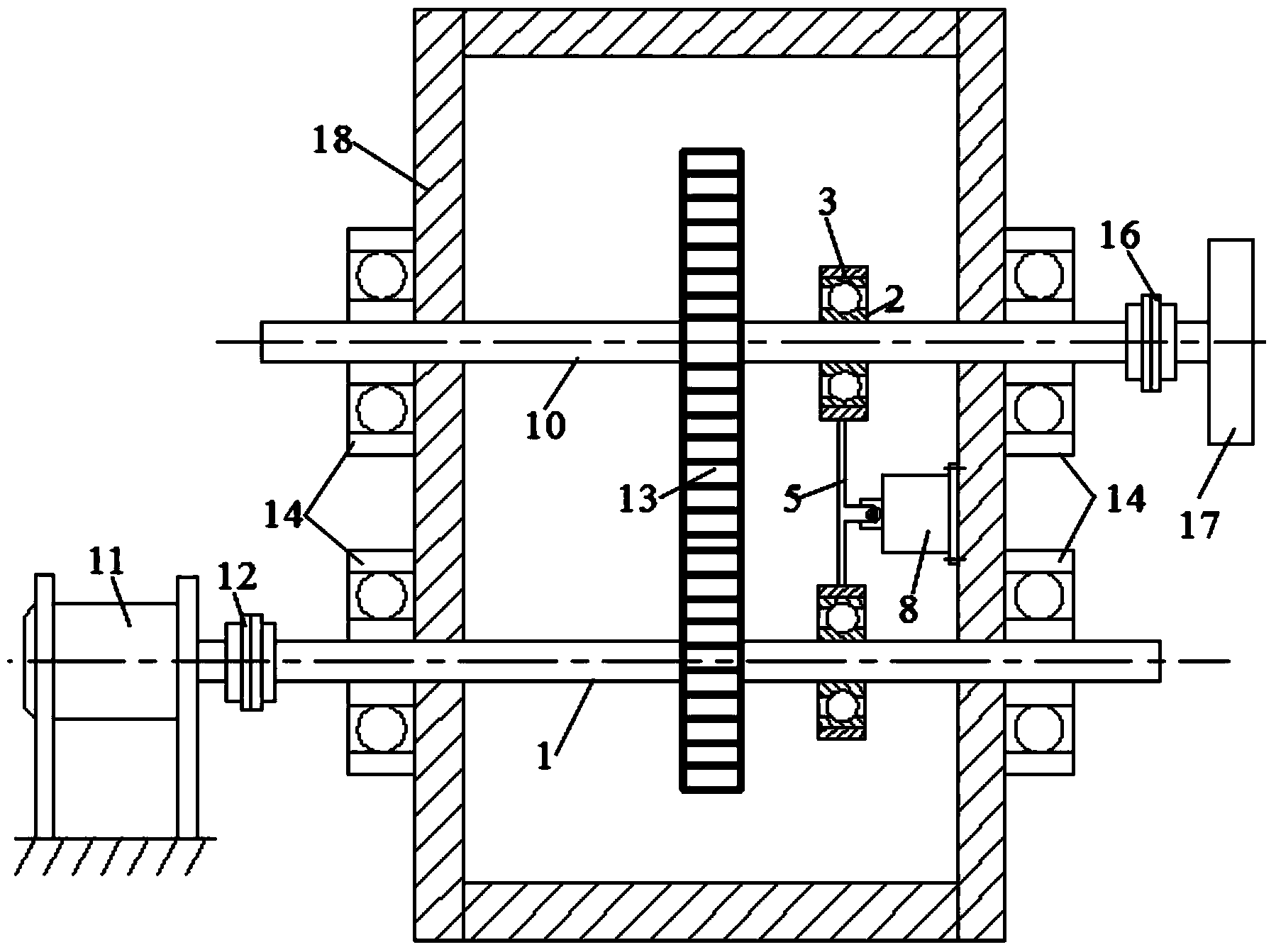
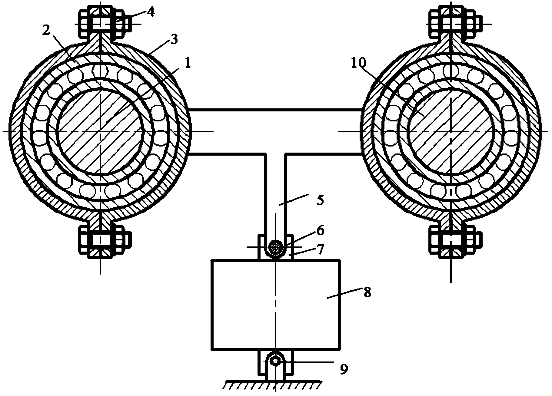
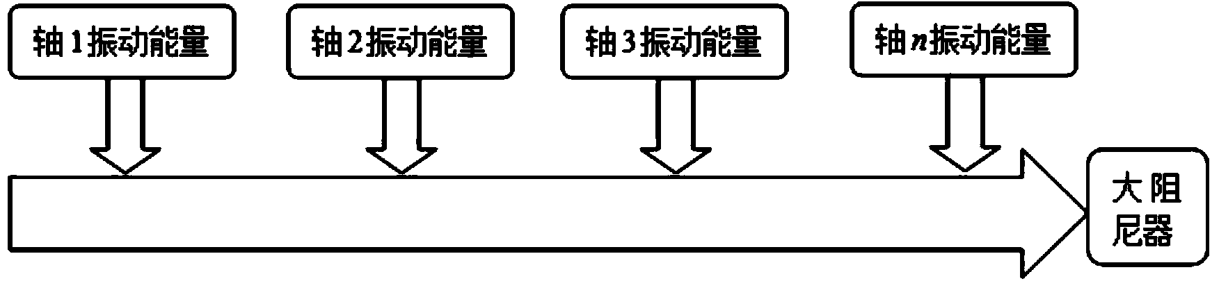
[0051] See attached Figure 8 , for a multi-stage transmission gearbox, in order to achieve a more ideal vibration reduction effect, it is also possible to install auxiliary bearings 2 and clamps 3 on each transmission shaft, and then collect the vibration of all transmission shafts through the designed vibration transmission link 5 Get up and pass to the large damping device 8. The damping device can be installed on the inner side wall, the top wall or the outside of the box according to the space of the box.

Embodiment 3

[0053] See attached Figure 9 , which is a worm transmission used to transmit motion and power between spatially interleaved axes. Due to the relatively high sliding speed between the meshing teeth of the worm gear and worm, it is easy to cause friction and wear of the gear teeth and cause vibration of the gear shaft and the box. The damping and vibration reduction device is also applicable to the worm drive with interleaved axes in space. Similarly, auxiliary bearings 2 and hoops 3 can be installed at the appropriate positions of the input shaft 1 of the worm 20 and the output shaft 10 of the turbine 21, and then the vibration of the staggered shaft system can be transmitted to the large damper 8 through the vibration transmission link 5 to reduce the vibration. The purpose of vibration and noise reduction is to improve the stability and life of the worm drive.


PUM


Abstract

The invention relates to a composite damping device for vibration and noise reduction of gear shafting, which belongs to the technical field of damping devices. The composite damping device acts on each gear shaft through an auxiliary bearing, a clamp and a vibration transmission frame with a flexible structure, vibration, which is generated by some factors in a process of transmission, of a gear pair is transferred to the auxiliary bearing, and the clamp and the vibration transmission frame so as to drive a piston soaked in high-viscosity damping liquid to do shearing motion in the damping liquid, generate a damping force large enough and absorb and dissipate vibration energy, thereby suppressing bending vibration of the shaft. On one hand, internal excitation of the whole gear is reduced, on the other hand, vibration which is transferred to a gearbox body is attenuated. By virtue of the composite damping device disclosed by the invention, the vibration of frequency components due to meshing impact in the gear shafting can be simultaneously reduced, and a vibration frequency band is wide. The composite damping device has the advantages of simple structure, easiness in removal and installation, flexibility of installation position, no worn parts, long service life and the like.

Description

technical field [0001] The invention mainly relates to a vibration reduction and noise reduction combined damping device installed in a gear shaft-to-gear transmission system, which can be used for vibration reduction and noise reduction of gear transmissions in the fields of wind power generators, aviation generators, steam turbines and other fields, and belongs to the technical field of damping devices . technical background [0002] As a general device for transmitting motion and power in mechanical equipment, gears and gearboxes play an important role in modern large-scale equipment such as metal cutting machine tools, aviation, power systems, transportation machinery, and metallurgical machinery. However, due to its complex structure and harsh working environment, when the gears are engaged in transmission, due to the influence of factors such as changes in external loads, gear processing and installation errors, time-varying gear meshing stiffness, and collision impact...

Claims


Application Information

Patent Timeline
Patent Type & Authority Applications(China)
IPC IPC(8): F16H57/028F16F15/023
CPCF16H57/0006
Inventor 何立东黄秀金王锎夏雪然黄文超高金吉
Owner BEIJING UNIV OF CHEM TECH
Why Eureka
Try Eureka