Coal seam gas adsorption and desorption deformation and deformation force dynamic test system

A technology of dynamic testing and coal seam gas, which is applied in the direction of measuring devices and instruments, can solve the problems of inability to effectively monitor acoustic emission signals, inability to test internal damage evolution laws, adsorption, desorption deformation, or single influencing factors of deformation force, etc., to achieve Simple structure, good sealing performance and wide application range

Inactive Publication Date: 2014-08-13
CHONGQING UNIV
View PDF5 Cites 20 Cited by
  • Summary
  • Abstract
  • Description
  • Claims
  • Application Information

AI Technical Summary

Problems solved by technology

Although these devices have advanced people's understanding of the characteristics and mechanism of coal rock adsorption and desorption deformation, there are still some shortcomings in the experimental conditions: 1. Most of the devices can only simply test the coal rock adsorption and desorption deformation , and then assume that the deformation force and deformation of the coal sample obey Hooke's law, and thus indirectly calculate the deformation force of the coal sample adsorption and desorption, but what is the relationship between the real adsorption and desorption deformation force and the deformation of the coal sample? Issues such as the law of evolution are worthy of further investigation
2. The factors affecting adsorption, desorption deformation or deformation force considered by these experimental devices are relatively single, and no device comprehensively considers gas pressure, temperature, strain conditions, initial stress, deformation, deformation force, and acoustic emission monitoring.
4. The acoustic emission signal of the test piece during the gas adsorption and desorption process cannot be effectively monitored, and the acoustic emission technology cannot be used to reveal the internal damage evolution law of the test piece during the gas adsorption and desorption process

Method used


Image

  • Coal seam gas adsorption and desorption deformation and deformation force dynamic test system
  • Coal seam gas adsorption and desorption deformation and deformation force dynamic test system
  • Coal seam gas adsorption and desorption deformation and deformation force dynamic test system

Examples


Embodiment 1

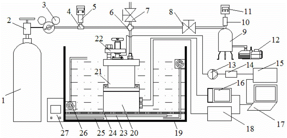
[0061] A coal seam gas adsorption / desorption deformation and deformation force dynamic testing system is characterized in that it includes a test tank system, a constant temperature system, an air pressure system and a measurement system.

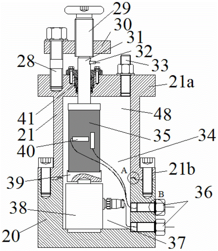
[0062] The test tank system includes a base 20, a tank body 21, a limit pressure rod 31, a load cell 38 and a limit mechanism. The base 20 is a hollow body with an open upper end and a closed lower end, and the tank body 21 is a hollow body with a closed upper end and an open lower end.

[0063] During the test, the lower end of the tank body 21 is fastened to the upper end of the base 20 , so that the inner cavity of the base 20 and the inner cavity of the tank body 21 together form an airtight test cavity 34 . see figure 2 , the inner cavity 48 of the tank is located on the upper part of the inner cavity 37 of the base, and the two together form the test cavity 34 . In this embodiment, the base 20 and the tank body 21 can be separated,...

Embodiment 2

[0071] The main structure of this embodiment is the same as that of Embodiment 1. Furthermore, a heating pipe 23 , a separator 24 , a temperature sensor 25 and a circulating water pump 26 are installed in the tank body 19 . The partition 24 is suspended in the tank body 19 , and the lower end of the base 20 is placed on the upper surface of the partition 24 . The heating pipe 23 is located below the partition 24 . The heating tube 23 is controlled by a temperature controller 27 installed outside the tank body 19 . The constant temperature water in the tank body 19 is driven to circulate by the circulating water pump 26 . The temperature sensor 25 is located outside the tank body 19, and is connected with the heating pipe 23 and the temperature sensor 25 through wires to control the water temperature.

[0072] During the test, the tank body 19 was filled with constant temperature water, and the base 20 and the tank body 21 were immersed in the constant temperature water. The...

Embodiment 3

[0074] The main structure of this embodiment is the same as that of Embodiment 1. Further, the limit mechanism of the test tank system is composed of a column 28 , a loading hand wheel 29 and a limit plate 30 .

[0075] The limiting plate 30 is located above the tank body 21 .

[0076] The lower end of the column 28 is fixed on the upper end of the tank body 21 . The upper end of the column 28 supports the limiting plate 30 .

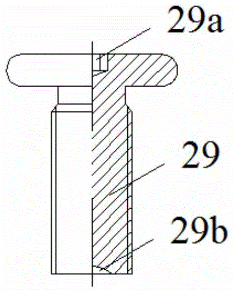
[0077] The loading hand wheel 29 is installed above the limiting plate 30 . The lower end of the loading hand wheel 29 is connected with a telescopic rod. In the embodiment, the loading hand wheel 29 and the telescopic rod are integrally formed, and its section is "T" shape. The limiting plate 30 has a screw hole through which the telescopic rod passes. After the lower end of the telescoping rod is screwed into the screw hole on the limiting plate 30 , it contacts with the upper end of the limiting pressing rod 31 . Further, an inner hexagonal groo...


PUM


Abstract

The invention provides a multifunctional test system capable of simultaneously and directly testing deformation and deformation force in coal body gas adsorption and desorption processes. The problem that coal body changes caused by gas adsorption and desorption can not be truly and reliably tested under the condition of a laboratory can be solved. The coal seam gas adsorption and desorption deformation and deformation force dynamic test system comprises a test tank system, a constant temperature system, a pressure system and a measuring system. The test tank system comprises a base, a tank body, a limiting pressing rod, a force transducer and a limiting mechanism. The constant temperature system comprises a tank body with the upper end open. The pressure system comprises a high-pressure gas storage steel cylinder, a cylinder valve, a four-way joint, a vent valve, a vacuum valve and a vacuum pump. The measuring system comprises a resistance strain gauge, a strain collection instrument, an acoustic emission sensor and an acoustic emission collection device. According to the test system, direct reliable tests on deformation and deformation force in the coal body gas adsorption and desorption processes under different gas pressure conditions, different temperature conditions, different strain conditions and / or different initial stress conditions can be achieved.

Description

technical field [0001] The invention relates to a test device, in particular to a test device and method for measuring coal body deformation and deformation force in the process of coal body adsorption and desorption of gas. Background technique [0002] Mine gas is generated in the metamorphic stage of coal, and mainly occurs in the state of being adsorbed on the surface of micropores and pressured in the pores and cracks of coal rock mass. The coal body-surrounding rock system is in a relatively static equilibrium state under the combined action of gas pressure and gas. When underground mining activities enter the coal seam and its surrounding rock, this equilibrium state is disturbed, resulting in the redistribution of the stress field of the coal rock mass and the re-migration of gas in the coal rock seam. In the process of changing the equilibrium state, in addition to the stress of the surrounding rock, the change of the microstructure of the coal body is also affecte...

Claims


Application Information

Patent Timeline
Patent Type & Authority Applications(China)
IPC IPC(8): G01D21/02
Inventor 曹树刚张遵国刘延保李勇郭平
Owner CHONGQING UNIV
Why Eureka
Try Eureka