Magnetic resistance Z-axis gradient sensor chip

A gradient sensor and magnetoresistance technology, applied in the field of magnetic sensors, can solve the problems of poor stability, low magnetic field sensitivity of Hall effect sensors, and difficulty in controlling offset and sensitivity changes.

Active Publication Date: 2014-08-20
MULTIDIMENSION TECH CO LTD
View PDF5 Cites 23 Cited by
  • Summary
  • Abstract
  • Description
  • Claims
  • Application Information

AI Technical Summary

Problems solved by technology

[0005] 3) Compared with GMR and TMR sensors, Hall effect sensors have lower magnetic field sensitivity, poor stability (sensitivity, offset and resistance), and poor repeatability (difficult to control offset and sensitivity changes)

Method used


Image

  • Magnetic resistance Z-axis gradient sensor chip
  • Magnetic resistance Z-axis gradient sensor chip
  • Magnetic resistance Z-axis gradient sensor chip

Examples


Embodiment 1

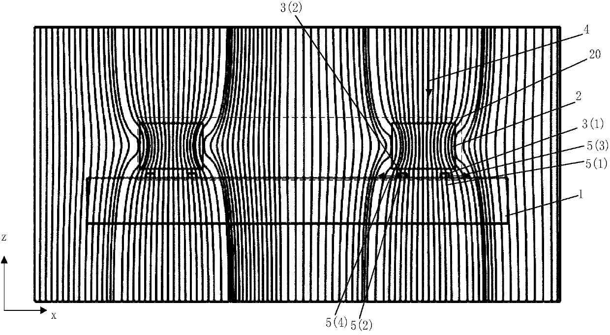
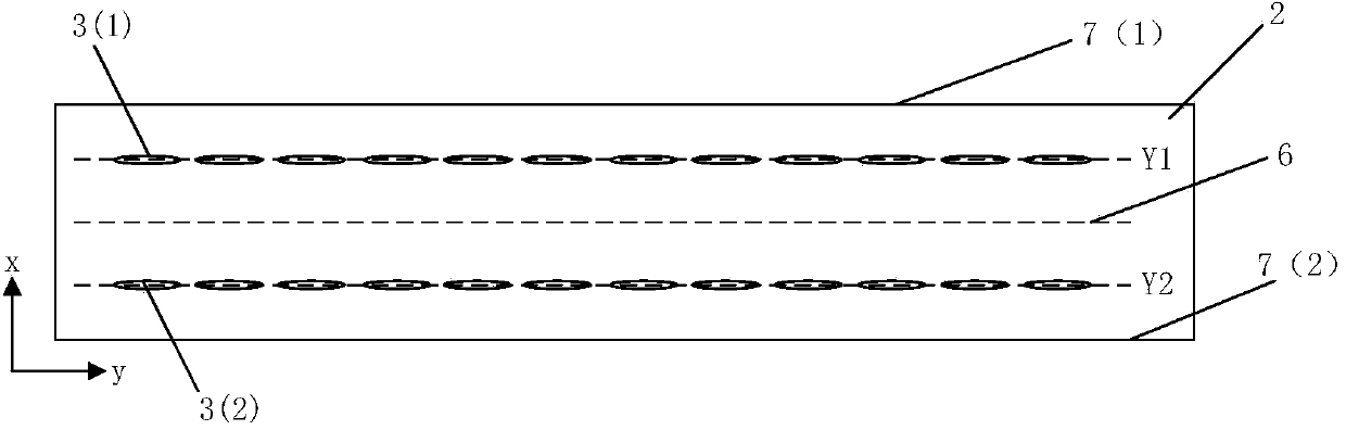
[0048] figure 1 It is a schematic diagram of a magnetoresistance Z-axis gradiometer chip, including a Si substrate 1, a magnetoresistance Z-axis sensor 20, and the magnetoresistance Z-axis sensor 20 is located on the Si substrate 1, and the magnetoresistance Z-axis sensor includes 2 or 2 groups containing multiple A magnetic flux guide 2 and a magnetoresistive unit 3 (including 3(1) or 3(2) in the figure), the magnetoresistive unit 3 is located above or below the flux guide 2, for simplicity, this figure only shows the magnetic The case where the resistance unit 3 is located below the flux guide 2 actually also includes the case where the magnetoresistive unit 3 is located above the flux guide 2 . The magnetic resistance unit 3 is electrically connected to form a half-bridge or full-bridge gradiometer. figure 1 The measurement principle of the Z-axis magnetic field is also given. After the Z-axis magnetic field 4 passes through the flux guide 2, since the flux guide 2 is a hi...

Embodiment 2

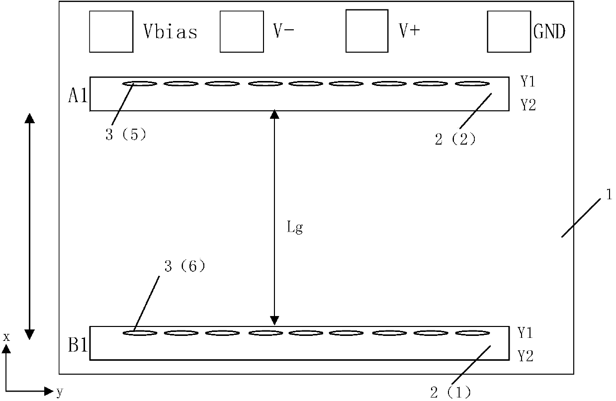
[0052] image 3 and Figure 4 It is another type of magnetoresistive Z-axis half-bridge gradient sensor chip and its electrical connection diagram, wherein the magnetoresistive units 3(5) and 3(6) on the two bridge arms of the half-bridge are respectively located in the flux guide In A1 and B1, and their occupied positions are the same, they are both located at Y1 or Y2, for the convenience of explanation, image 3 , 4 Only the case of being in the same Y1 position and having the same magnetic field sensitivity direction is given. At this time, the output signal of the half bridge can be calculated according to the following method:

[0053] After the Z-axis magnetic field HZ passes through the flux director, the X-axis direction magnetic field HX is obtained. The relationship between HZ and HX is:

[0054] HX1=HZ1*SXZ (1)

[0055] HX2=HZ2*SXZ (2)

[0056] Among them, SXZ is the magnetic field conversion parameter of the flux director, which is related to the geometric st...

Embodiment 3

[0066] Figure 5-7 It is a structural schematic diagram of a gradient sensor chip with a full-bridge structure and an electrical connection diagram of five corresponding magnetoresistance units. Figure 5 In , the corresponding positions Y1 and Y2 of the flux guides A1 and B1 are respectively occupied by the magnetoresistive units 3(7)-3(10) corresponding to the four bridge arms of the full bridge, where Figure 6 Among them, the two half-bridges of the full bridge correspond to the flux guides A1 and B1 respectively, the magnetoresistive units at the Y1 and Y2 positions of each flux guide have the same magnetic field sensitivity direction, and the two bridges connected to the electrodes The magnetoresistive units of the arms have the same magnetic field sensitivity direction. Figure 5 The output signal of the full bridge structure gradient sensor chip shown is shown in equations (5)-(7), and the measured Z-axis magnetic field gradient is shown in equation (8):

[0067] V-=...


PUM


Abstract

The invention discloses a magnetic resistance Z-axis gradient sensor chip which is used for detecting the gradients of components of a Z-axis magnetic field generated by magnetic media in the X-Y plane so as to conduct magnetic imaging on the magnetic media. The magnetic resistance Z-axis gradient sensor chip comprises a Si substrate, two or two groups of sets containing a plurality of flux leaders and magnetic resistance sensing units which are electrically connected, wherein the distance between the sets is Lg. The magnetic resistance sensing units are located on the Si substrate and located above or below the edges of the flux leaders, the components of the Z-axis magnetic field are converted into the mode that the components of the Z-axis magnetic field are parallel to the surface of the Si substrate and in the direction of the sensitive axes of the magnetic resistance sensing units, and the magnetic resistance sensing units are electrically connected into a half-bridge or whole-bridge gradient meter, wherein the distance between opposite bridge arms is Lg. The sensor chip can be used together with a PCB, a PCB and back magnetor a PBC and back magnet and packaging shell. According to the magnetic resistance Z-axis gradient sensor chip, measurement of the Z-axis magnetic field gradient is achieved by using plane sensitive magnetic resistance sensors, and the magnetic resistance Z-axis gradient sensor chip has the advantages of being small in size and low in power consumption, having higher magnetic field sensitivity than a Hall sensor and the like.

Description

technical field [0001] The invention relates to the field of magnetic sensors, in particular to a magnetoresistance Z-axis gradient sensor chip. Background technique [0002] Magnetoresistive gradient sensors are widely used in gear speed sensors and magnetic image sensors, such as POS machine magnetic heads, banknote detector magnetic heads, etc. Usually, magnetoresistive sensors such as GMR and TMR sensors have planar sensitive units whose magnetic field sensitivity direction is parallel to the sensor The chip plane where it is located, while the Hall sensor has a Z-axis sensitive direction perpendicular to the plane. At present, when the Hall sensor is used in a magnetic image sensor, there are mainly Hall effect magnetic heads of Murata's InSb thin film material, which are measured based on the Z-axis magnetic field component. However, whether it is a Hall sensor based on the Z-axis magnetic field component for measurement, or a GMR and TMR sensor based on the in-plane m...

Claims


Application Information

Patent Timeline
Patent Type & Authority Applications(China)
IPC IPC(8): G01R33/022
CPCG01R33/022G01R33/0011G01R33/093G01R33/098G01R33/0094G01R33/09
Inventor 詹姆斯·G·迪克周志敏
Owner MULTIDIMENSION TECH CO LTD
Why Eureka
Try Eureka