Improved type desulfurization and denitrification spray gun

An improved technology for desulfurization and denitrification, which is applied to the separation of dispersed particles, chemical instruments and methods, and separation methods. Pipe material consumption, enhanced effect and efficiency, effect of improved cooling effect

Inactive Publication Date: 2014-08-27
姜建勇
View PDF3 Cites 4 Cited by
  • Summary
  • Abstract
  • Description
  • Claims
  • Application Information

AI Technical Summary

Problems solved by technology

[0004] At present, in desulfurization and denitrification, flue gas conditioning and other processes, it is necessary to spray the fluid to a certain position with a spray gun to achieve an ideal mixing effect; when in use, the spray gun is in high-temperature flue gas, and over time, the high-temperature flue gas will make the The spray gun and the fluid in the barrel are overheated, and the fluid tends to vaporize in the barrel, causing the pressure in the spray gun to rise. Due to the change in the pressure in the barrel, the fluid cannot be sprayed to a certain position with the expected particle size, which is not ideal. The blending effect of
[0005] In addition, the increase in the internal pressure of the strong pipe caused by fluid gasification can lead to the bursting of the spray gun in severe cases, and the service life is short, which affects the safety of equipment and operators. The above problems have been technical problems for many years and urgently need to be solved.

Method used


Image

  • Improved type desulfurization and denitrification spray gun
  • Improved type desulfurization and denitrification spray gun

Examples


Embodiment Construction

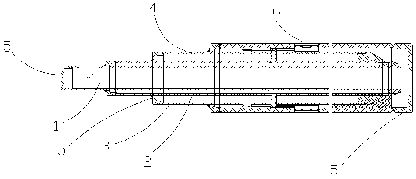
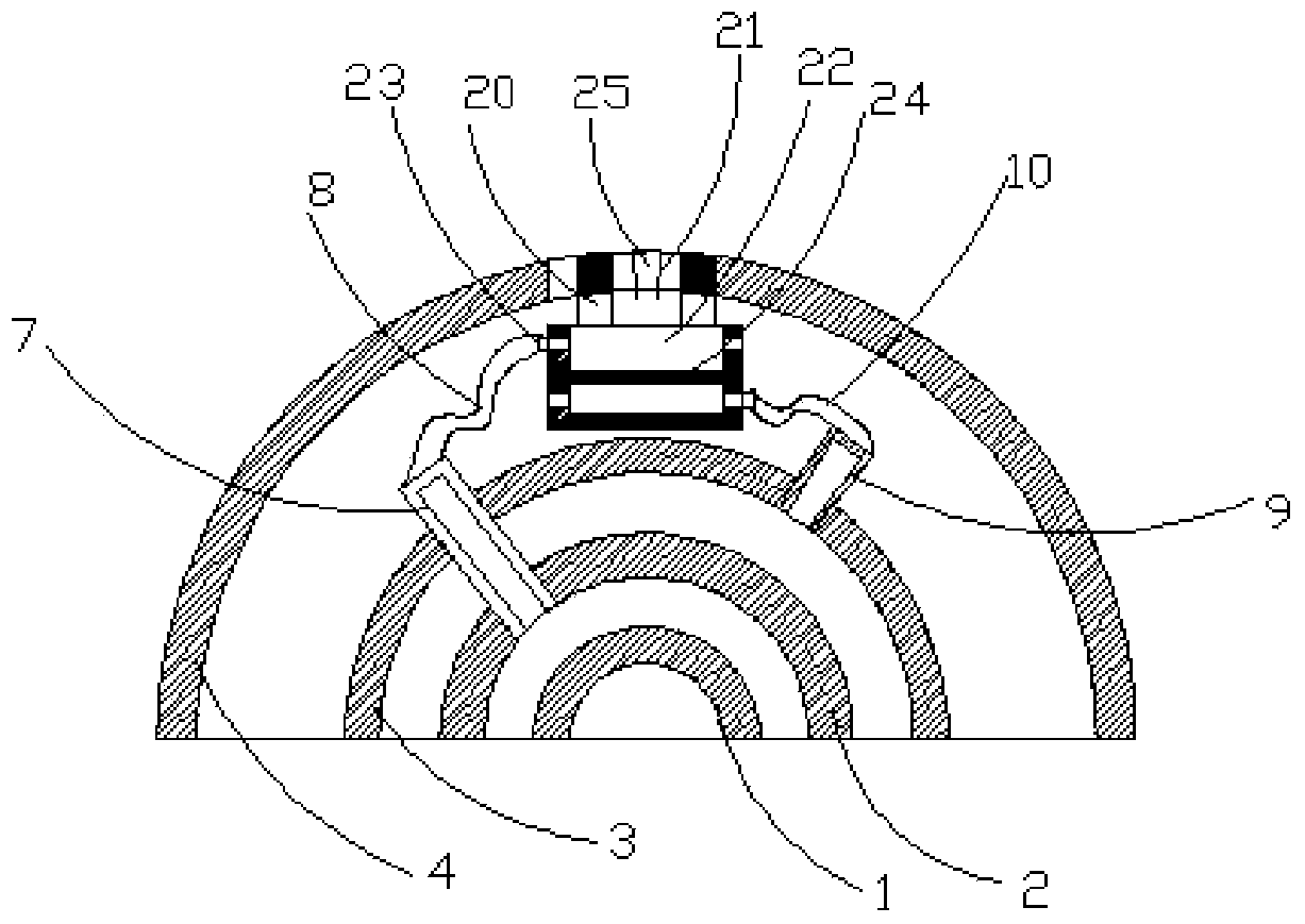
[0019] Such as figure 1 and figure 2 As shown, the present invention relates to an improved desulfurization and denitrification spray gun, which is characterized in that it includes a first pipe 1, a second pipe 2, a third pipe 3 and a fourth pipe arranged in sequence from the inside to the outside and connected to each other at intervals with a support ring. Pipe 4, one end of the first pipe 1 is blocked and sealed with a head 5, and the other end forms a port; the two ends of the second pipe 2 and the outer wall of the first pipe 1 are blocked and sealed with a head 5 ; The two ends of the third pipe 3 and the outer wall of the second pipe 2 are blocked and sealed with a head 5; between one end of the fourth pipe 4 and the outer wall of the third pipe 3 are blocked with a head 5 seal, the other end is sealed separately with the head 5; on the tube wall of the fourth tube 4, there are a plurality of radial and axially spaced nozzle assemblies 6, and on the tube wall of the ...


PUM


Abstract

The invention discloses an improved type desulfurization and denitrification spray gun which comprises a first tube, a second tube, a third tube and a fourth tube which are arranged in sequence from inside to outside and are connected at intervals through support rings, wherein one end of the first tube is blocked by an end plug for sealing; a through hole is formed in the other end of the first tube; the part between each of two ends of the second tube and the outer wall of the first tube is sealed by using an end seal; the part between each of two ends of the third tube and the outer wall of the second tube is sealed by using an end seal; the part between one end of the fourth tube and the outer wall of the third tube is sealed by using another end seal; the other end of the fourth tube is sealed by using another end seal; a plurality of nozzle components which are arranged at intervals in the radial direction and the axial direction are arranged on the wall of the fourth tube; a plurality of second connectors which face outwards are formed on the wall of the second tube; the second connectors penetrate through the wall of the third tube; urea tubes are arranged among the second connectors and the nozzle components; a plurality of convex third connectors are formed on the wall of the third tube; air tubes are arranged among the third connectors and the nozzle components. By adopting the spray gun, the desulfurization and denitrification working efficiency is improved, meanwhile the service life is prolonged, and the use cost is lowered for companies.

Description

technical field [0001] The invention relates to a spray gun used in desulfurization and denitrification operations. Background technique [0002] The desulfurization and denitrification tower is mainly composed of a flue gas conveying system, an absorption tower, a spray system, a slurry circulation system, and a slurry recovery system. [0003] The industrial waste gas transports a large amount of sulfur dioxide, carbon dioxide, etc. waste gas to the absorption tower through the flue gas conveying system. A large amount of desulfurization agent in the absorption tower is transported to the tower body by the spray system. The desulfurizer and industrial waste gas with a certain pressure and detachment ability Full contact produces a chemical reaction. In order to make the sulfur dioxide in the waste gas form a precipitate and flow to the bottom of the tower, it is discharged from the slurry circulation system to the outside of the tower for recycling. After desulfurization a...

Claims


Application Information

Patent Timeline
Patent Type & Authority Applications(China)
IPC IPC(8): B01D53/78B01D53/60
Inventor 徐建明
Owner 姜建勇
Why Eureka
Try Eureka