A continuous annealing device for thermochromic coating materials on sheet substrates

A thermochromic coating and annealing device technology, applied in heat treatment furnaces, heat treatment equipment, furnaces, etc., can solve problems such as unsuitable thermochromic smart glass annealing treatment, unfavorable safety performance of glass heating, etc., to shorten production time and reduce tempering stress The effect of low loss and low overall temperature rise

Active Publication Date: 2016-08-24
GUANGZHOU INST OF ENERGY CONVERSION - CHINESE ACAD OF SCI
View PDF7 Cites 0 Cited by
  • Summary
  • Abstract
  • Description
  • Claims
  • Application Information

AI Technical Summary

Problems solved by technology

Although the device can realize annealing in a vacuum environment, the heating device is located below the track, which is also not suitable for the annealing treatment of thermochromatic smart glass, and the heating of the glass by the lower heat radiation is not conducive to the control of safety performance.

Method used


Image

  • A continuous annealing device for thermochromic coating materials on sheet substrates
  • A continuous annealing device for thermochromic coating materials on sheet substrates
  • A continuous annealing device for thermochromic coating materials on sheet substrates

Examples


Embodiment 1

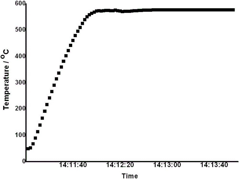
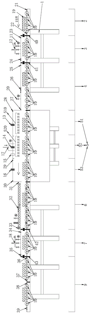
[0053] Taking tempered glass as the substrate coated with thermochromatic coating materials as an example, such as Figure 1-6 The shown continuous annealing device for thermochromic coating materials on sheet substrates includes a working platform 1 . The working platform 1 is provided with a feeding area 2 and a feeding area 9 . Several functional units are arranged between the loading area 2 and the unloading area 9, which are the first vacuum chamber 3, the heat treatment chamber and the second vacuum chamber 7 in sequence. The chambers are separated by dynamic airtight doors. The heat treatment chamber can also be divided into a vacuum zone 4, a heat treatment zone 5 and a cooling zone 6 according to functions. The heat treatment area 5 can also be divided into a preheating section 51 , an annealing section 52 and an isolation section 53 according to functions.

[0054] like figure 1 As shown, the working platform 1 is provided with a transmission mechanism composed o...

Embodiment 2

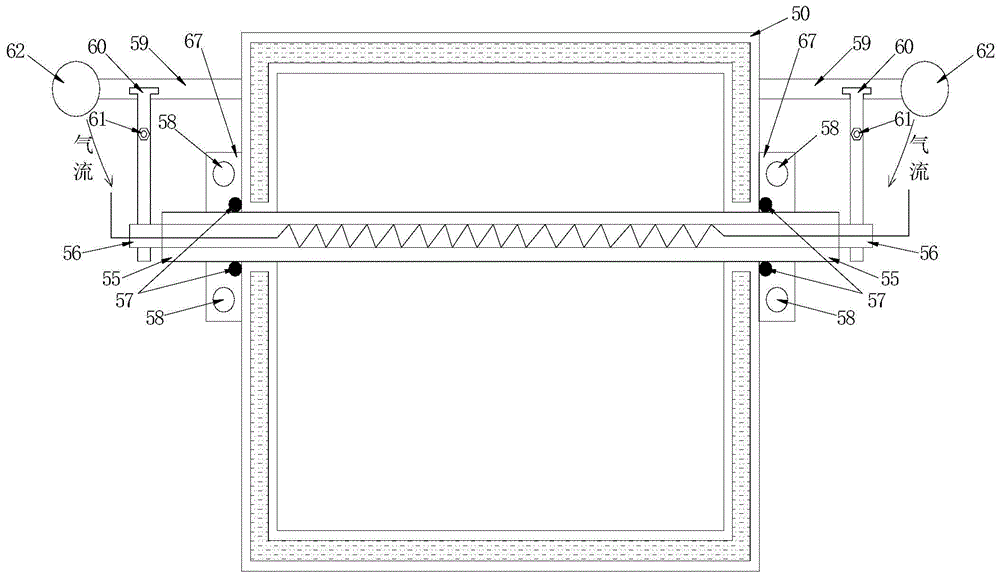
[0072] like Figure 10 and 11 As shown, the difference between Embodiment 2 and Embodiment 1 is that an air grid quenching zone 8 is also provided between the second vacuum chamber 7 and the feeding zone 9 . like Figure 8 As shown, a set of independently operable transfer rollers 10 is also provided in the air grid quenching zone 8 . A plurality of arranged air ducts are arranged above and below the transmission mechanism, which are respectively a first air duct 81 and a second air duct 82 . Several air nozzles 83 are opened on each air pipe. After the substrate enters the air grid quenching zone 8 from the second vacuum chamber 7, the blower blower connected with the first air pipe 81 and the second air pipe 82 blows the air along the air flow. Blow toward the substrate in the airflow direction shown in the figure to achieve the purpose of rapid cooling.

[0073] The substrate containing the thermochromic coating material on the surface enters the rapid cooling zone 8 of...


PUM


Abstract

The invention discloses a continuous annealing device for thermochromic coating materials on sheet-like substrates, which includes a working platform, which is provided with a feeding area, a working area and a feeding area; and also includes a transmission mechanism, which passes through the The entire feeding area, working area and unloading area; in the working area, a heat treatment chamber and several vacuum chambers are arranged on the working platform; the heat treatment chamber is arranged between the vacuum chambers and separated from the vacuum chamber by a sealing device ; The heat treatment chamber includes a working cavity, the working cavity is a double-layer structure, including an inner cavity and an outer wall, a cooling interlayer for flowing coolant is provided between the inner cavity and the outer wall, and the inner surface of the inner cavity is coated with a heat-absorbing coating layer; the heat treatment chamber communicates with the vacuum pump group. The invention can process workpieces of different sizes at the same time, and the temperature in the device can be freely adjusted from room temperature to 700°C, greatly shortening the production time of annealing to meet the needs of mass production.

Description

technical field [0001] The invention relates to an annealing device, in particular to a continuous annealing device for thermochromic coating materials on sheet substrates. Background technique [0002] Due to the pressure of energy shortage, countries all over the world are paying great attention to the field of building energy conservation, which accounts for one-third of the total energy consumption of the society, especially the energy conservation of building doors and windows has become the focus of attention. For this reason, LOW-E energy-saving door and window glass has been widely used, but the optical properties cannot be changed with people's will or environmental conditions, and its comfort and energy-saving effects have limitations. In contrast, thermochromic coating materials, especially thermochromic smart glass, have the function of controlling heat gain as the ambient temperature changes, and its energy-saving effect is more obvious, and it has become the ch...

Claims


Application Information

Patent Timeline
Patent Type & Authority Patents(China)
IPC IPC(8): C21D1/26C21D9/46
Inventor 徐刚詹勇军熊斌黄华凛孙耀明
Owner GUANGZHOU INST OF ENERGY CONVERSION - CHINESE ACAD OF SCI
Why Eureka
Try Eureka