Supercharge Your Innovation With Domain-Expert AI Agents!

A New Air Separator for Ammonia Refrigeration

An air separator and ammonia refrigeration technology, applied in the field of separators, can solve the problems of excessive power consumption of compressors, low total heat transfer coefficient, large mass transfer resistance, etc., and achieve easy operation and maintenance, broad market prospects, and improved work efficiency effect

Active Publication Date: 2016-01-20
JINAN GAORUI BIOTECH CO LTD
View PDF6 Cites 0 Cited by
  • Summary
  • Abstract
  • Description
  • Claims
  • Application Information

AI Technical Summary

Problems solved by technology

[0004] To achieve condensation, ammonia vapor must pass through the air film in the form of diffusion, resulting in a large mass transfer resistance, which directly reduces the total heat transfer coefficient to a very low level, seriously affecting the condensation process
Once the condensing pressure rises, the discharge pressure of the compressor will directly rise, causing the power consumption of the compressor to seriously exceed the standard, resulting in deterioration of the cooling effect, so the air in the system must be removed
[0005] Although there is an air separator in the ammonia refrigeration system, due to the limitation of the function of the traditional air separator, the heat transfer coefficient is low, and the air cannot be automatically removed, so it is inconvenient to operate and it is difficult to completely remove the air in the system

Method used


Image

  • A New Air Separator for Ammonia Refrigeration
  • A New Air Separator for Ammonia Refrigeration

Examples


Embodiment Construction

[0024] Now in conjunction with accompanying drawing, the present invention is described in further detail.

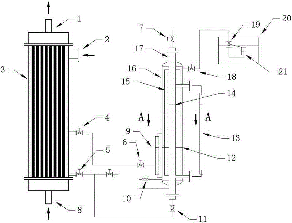
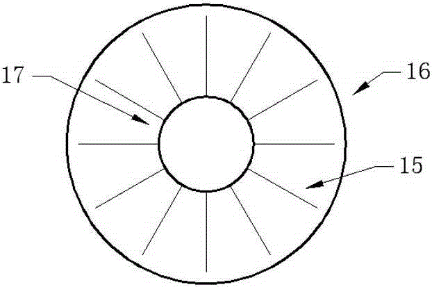
[0025] Such as figure 1 and figure 2 The new air separator for ammonia refrigeration shown includes a tube heat exchanger 3, the lower tube side of the tube heat exchanger is connected to the cooling water inlet pipe 8, the upper tube side is connected to the cooling water outlet pipe 1, and the shell side of the tube heat exchanger is The top is provided with an air inlet 2, the bottom of the shell side is connected to the bottom of the inner cylinder 17 through the pipeline, the valve 5 and the expansion valve 11, and the top of the inner cylinder 17 is connected to the low pressure end of the ammonia refrigeration system through the pipeline and the valve 7; There is an outer cylinder 16, the outer wall of the inner cylinder 17 and the inner wall of the outer cylinder 16 form a sealed cavity, and the outer wall of the inner cylinder is welded with a finned plate 15...


PUM


Abstract

The invention discloses a novel ammonia refrigeration air separator which comprises a shell-and-tube heat exchanger. A lower tube pass of the shell-and-tube heat exchanger is connected with a cooling water inlet tube, an upper tube pass of the shell-and-tube heat exchanger is connected with a cooling water outlet tube, a gas inlet is formed in the top of a shell pass of the shell-and-tube heat exchanger, the bottom of the shell pass is communicated with the bottom of an inner barrel through a pipeline, a valve and an expansion valve, and the top of the inner barrel is communicated with the low-pressure end of an ammonia refrigeration system through a pipeline and a valve. An outer barrel is arranged outside the inner barrel, a sealed cavity is formed between the outer wall of the inner barrel and the inner wall of the outer barrel, and a fin plate is welded to the outer wall of the inner barrel, and is located in the sealed cavity. The lower middle portion of the shell pass of the shell-and-tube heat exchanger is communicated with the lower portion of the sealed cavity through a pipeline and a valve, and the upper portion of the sealed cavity is connected with an exhaust device. A cavity formed by the inner wall of the inner barrel is communicated with the sealed cavity through a pipeline and an expansion valve. The novel ammonia refrigeration air separator is good in heat exchange efficiency, air is removed thoroughly, the air can be exhausted automatically, the structure is simple, high practicality is achieved, and the prospect is wide.

Description

technical field [0001] The invention relates to a separator for removing air in an ammonia refrigeration device. Background technique [0002] Ammonia has excellent thermodynamic properties, and ammonia is generally used as a refrigerant in larger refrigeration systems. In the four-step cycle of compression, condensation, throttling, and evaporation of refrigeration, the condensation of ammonia is one of the four-step cycles. The ammonia condenser uses the heat exchange of circulating water to realize the condensation and liquefaction of ammonia vapor. The general design pressure of the ammonia condenser is close to 2.5MP, is a typical pressure vessel. [0003] In the condensation cycle of ammonia, the total heat transfer coefficient is affected by many factors, among which the non-condensable gas mixed in it is greatly affected. The non-condensable gas in actual production is generally air, because in the condensation process of ammonia vapor In the process, the ammonia v...

Claims


Application Information

Patent Timeline
Patent Type & Authority Patents(China)
IPC IPC(8): F25B43/04
Inventor 银永忠
Owner JINAN GAORUI BIOTECH CO LTD
Features
  • R&D
  • Intellectual Property
  • Life Sciences
  • Materials
  • Tech Scout
  • Unparalleled Data Quality
  • Higher Quality Content
  • 60% Fewer Hallucinations
Learn More