Efficient-heat-dissipation integrated LED modulator tube structure and production process thereof

A technology of LED lamp tube and production process is applied in the field of integrated LED lamp tube structure with high efficiency and heat dissipation to achieve the effects of improving light output efficiency, improving heat dissipation coefficient and saving reactive power loss

Inactive Publication Date: 2014-09-03
GUANGDONG JINYUAN LIGHTING TECH
View PDF6 Cites 2 Cited by
  • Summary
  • Abstract
  • Description
  • Claims
  • Application Information

AI Technical Summary

Problems solved by technology

[0010] In view of the above defects, the present invention aims at the problems of heat dissipation, light decay, light color and light output efficiency in white LED packaging technology, and proposes an efficient heat dissipation integrated LED lamp tube structure and its production process to solve many problems in the prior art. Insufficient, the structure is to print the circuit directly on the surface of the heat sink of the lamp shell by using micro-wiring technology, and then solder the chip on the heat sink of the light tube shell with the printed circuit, canceling the bracket and aluminum substrate in the traditional structure; And fill the transparent heat-conducting silica gel between the phosphor powder and the chip, so that the phosphor powder and the chip are separated, and the electronic components of the drive circuit are directly welded on the heat sink of the lamp tube shell

Method used


Image

  • Efficient-heat-dissipation integrated LED modulator tube structure and production process thereof
  • Efficient-heat-dissipation integrated LED modulator tube structure and production process thereof

Examples


Embodiment Construction

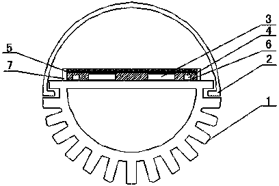
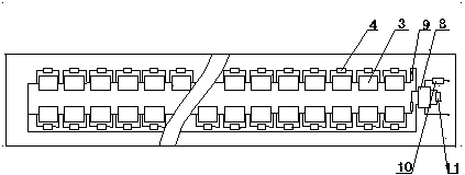
[0035] Such as Figure 1-2 As shown, the integrated LED tube with efficient heat dissipation according to the embodiment of the present invention includes an aluminum shell 1 and a PC cover 2. The PC cover 2 has a semi-circular structure and the horizontal end surface of the PC cover 2 and the aluminum shell 1 The horizontal end faces are fixed and spliced. The aluminum shell 1 is made of metal aluminum with high thermal conductivity (120~200 W / m·K) and has a semicircular cross-section, which is uniformly opened on the outer arc wall of the aluminum shell 1 Several grooves play the role of heat dissipation. The horizontal wall surface of the aluminum shell 1 is the packaging plane. Before packaging, the packaging plane of the aluminum tube is coated with an insulating layer composed of epoxy resin, oxide, and polymer materials. After baking and hardening, the circuit layer is printed with micro-wiring technology on the insulating layer, and then a white UV curing solder mask (S...


PUM


Abstract

The invention relates to an efficient-heat-dissipation integrated LED modulator tube structure and a production process of the efficient-heat-dissipation integrated LED modulator tube structure. The horizontal wall of an aluminum shell is a packaging plane. A printed circuit layer is arranged on the packaging plane. Chips are welded to the printed circuit layer of the aluminum shell. A silica gel layer is arranged in the area defined by a surrounding glue layer of the aluminum shell. The upper surface of the silica gel layer is evenly coated with a fluorescent powder coating. An intelligent IC drive element is directly welded to the printed circuit layer of the aluminum shell. The two ends of each chip are connected with voltage regulator tubes respectively. The chip-support-aluminum substrate-tube body multistage thermal resistance obstacle is thoroughly omitted, the heat conduction way is improved, and the heat conduction distance is greatly shortened; a support and the aluminum substrate are omitted, and production cost is reduced; the problems that the luminous efficiency is low and the luminous decay becomes large are solved; no extra drive module is needed, and automatic attachment is completed; heat produced when the intelligent IC drive element and electronic elements work is directly transmitted outwards through aluminum pipes, and therefore the heat dissipation effect of a drive module is improved, and the service life of a power supply is prolonged.

Description

Technical field [0001] The invention relates to the technical field of LEDs, in particular to an integrated LED tube structure with high efficiency and heat dissipation and its production process. Background technique [0002] LED is an electroluminescent device, and its heat cannot be radiated away, but can only be conducted through the medium. If the thermal system design of the LED device is not perfect, and the thermal resistance from the PN junction to the external environment of the LED is too large, it will cause the PN junction junction temperature to be too high, and the subsequent thermal effect will become very obvious: the junction temperature increases, Directly reduce the photons emitted by the chip, and the light output efficiency is reduced; especially for the current implementation of white light where the phosphor is directly filled around the blue chip, too high temperature will seriously affect the characteristics of the phosphor, and ultimately lead to wavele...

Claims


Application Information

Patent Timeline
Patent Type & Authority Applications(China)
IPC IPC(8): F21S2/00F21V29/00F21V23/00H01L33/48H01L33/64H01L33/54H01L33/50F21Y101/02F21K9/90F21Y103/00F21Y115/10
Inventor 李立勉
Owner GUANGDONG JINYUAN LIGHTING TECH
Why Eureka
Try Eureka