Dual-CCD (Charge Coupled Device) scanning imaging detection method for continuous casting slab surface defects

A scanning imaging and detection method technology, applied in the field of iron and steel metallurgy, can solve the problems of recognition algorithm design and final recognition accuracy limit, it is difficult to ensure a reliable defect recognition rate, and phase unwrapping algorithm design is difficult, so as to ensure clear imaging High degree, easy on-line detection and industrial implementation, and the effect of eliminating high-temperature radiation interference

Inactive Publication Date: 2014-09-03
CHONGQING UNIV
View PDF10 Cites 59 Cited by
  • Summary
  • Abstract
  • Description
  • Claims
  • Application Information

AI Technical Summary

Problems solved by technology

Due to its strong adaptability to the environment, conventional optical detection methods have advantages in detecting the surface quality of high-temperature slabs. However, these current optical detection methods are limited by conventional CCD imaging. Because the surface of slabs is often covered with scales Due to the interference of false defect information such as iron oxide scale and vibration marks, defect images are often lost in high background noise images. Even if high-definition images are obtained, it is difficult to guarantee a reliable defect recognition rate. Therefore, the recognition algorithm design and final recognition accuracy are greatly affected. limit
The laser triangular slab

Method used


Image

  • Dual-CCD (Charge Coupled Device) scanning imaging detection method for continuous casting slab surface defects
  • Dual-CCD (Charge Coupled Device) scanning imaging detection method for continuous casting slab surface defects
  • Dual-CCD (Charge Coupled Device) scanning imaging detection method for continuous casting slab surface defects

Examples


Embodiment Construction

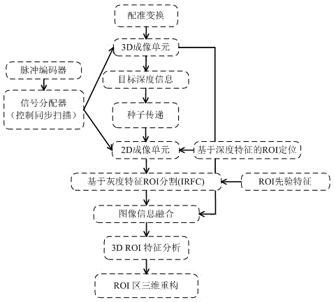
[0028] Before cutting the continuous casting slab or billet, it is the core content of this invention to accurately extract the image of the surface defect of the casting slab online, and to eliminate the surface vibration marks, iron oxide scale, residual mold slag layer and water film interference, and its purpose is to facilitate and reduce image recognition. The selection and extraction of the feature quantity of the area of ​​interest on the surface during the process improves the defect recognition rate, reduces errors, simplifies the design complexity of the system defect classifier, and provides reliable technical support for the continuous casting slab surface quality assessment. The realization idea is to combine the conventional grayscale linear array CCD scanning imaging method with the laser three-dimensional ranging mapping scanning imaging technology based on the area array CCD, and accurately extract the two-dimensional shape and three-dimensional depth features ...


PUM


Abstract

The invention discloses a dual-CCD (Charge Coupled Device) scanning imaging detection method for continuous casting slab surface defects. The dual-CCD scanning imaging detection method comprises the following steps: (1) mounting a linear array CCD camera, an area array CCD camera and a linear laser transmitter on a continuous casting slab; (2) scanning by the linear array CCD camera and the area array CCD camera according to a synchronous frame frequency and line frequency manner to obtain a two-dimensional image and a three-dimensional image of the surface of the continuous casting slab; (3) registering the acquired two-dimensional image and three-dimensional image; and (4) carrying out information fusion processing on the registered two-dimensional image and three-dimensional image in one area on the surface of the continuous casting slab, analyzing area-of-interest features of the two images, and extracting a final area-of-interest to be identified on the surface of the continuous casting slab by combining the feature fusion processing result of the two images, thus reserving reliable defect information of the surface of the casting slab and detecting the surface defects of the continuous casting slab. According to the dual-CCD scanning imaging detection method provided by the invention, the structure is simple and convenient; the method is high in detection precision, great in real-time property and capable of automatically eliminating interference information.

Description

technical field [0001] The invention relates to continuous casting slab defect detection technology, specifically a double CCD scanning imaging detection method for continuous casting slab surface defects. The invention relates to a surface imaging and defect detection system for hot-rolled strip steel and pickled steel strip, belonging to the technical field of iron and steel metallurgy. [0002] Background technique [0003] In the field of iron and steel metallurgy, high-temperature continuous casting slab hot delivery and hot charging and continuous casting-rolling, as a continuous production technology, provide a guarantee for enterprises to improve productivity, save energy and reduce consumption, and maintain modern market competitiveness. This technology has largely shortened the complex production process of iron and steel technology, and its economic benefits are obvious. With the rapid development and application of continuous casting and rolling in the domestic...

Claims


Application Information

Patent Timeline
IPC IPC(8): G01N21/88
Inventor 欧阳奇赵立明陈登福张兴兰彭松曾月斌陈希梦付统
Owner CHONGQING UNIV
Why Eureka
Try Eureka