Multiport back-to-back DC-DC converter
A DC converter and multi-port technology, applied in the direction of converting DC power input to DC power output, parallel operation of DC power supplies, instruments, etc., can solve problems such as lack of isolation of DC faults, stability problems, and inconvenient expansion, and achieve Improve the safety and stability of operation, save costs, and improve the effect of safety
- Summary
- Abstract
- Description
- Claims
- Application Information
AI Technical Summary
Problems solved by technology
Method used
Image
Examples
Embodiment 1
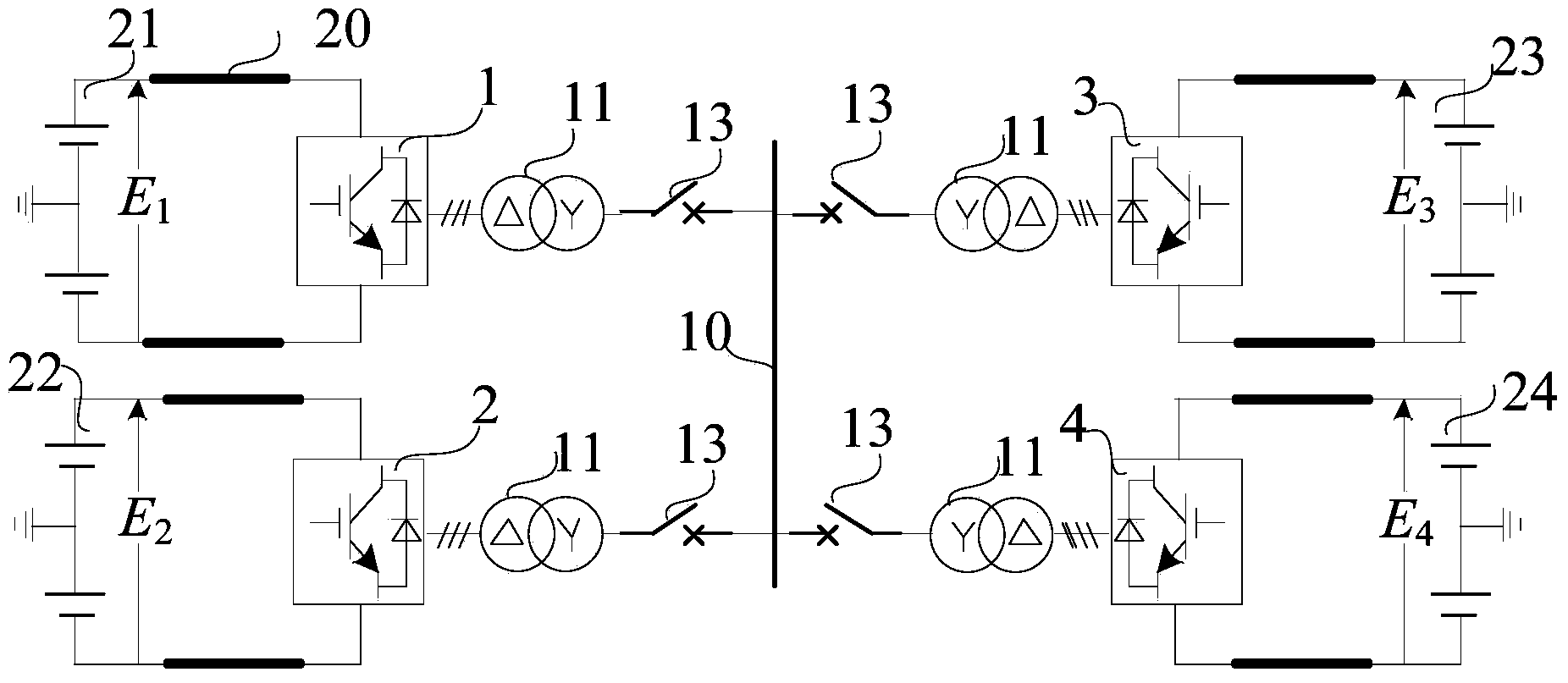
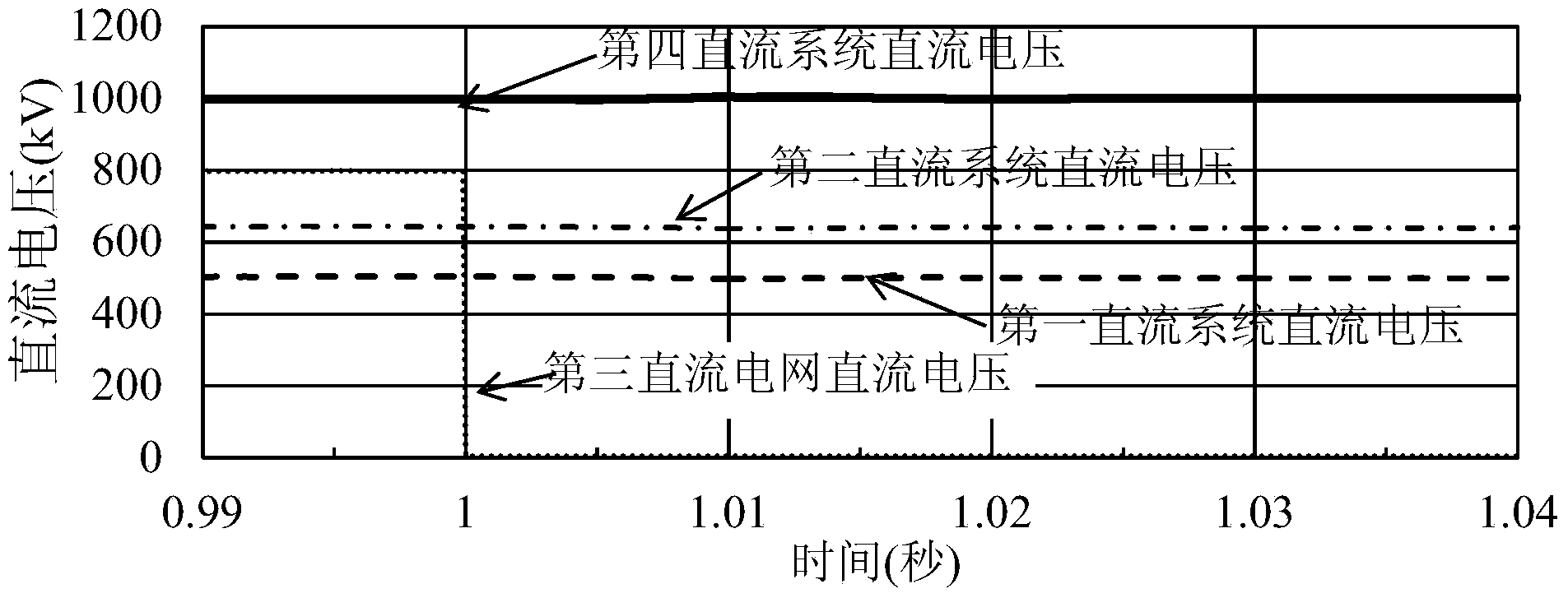
[0045] Such as Figure 7 The shown four-port back-to-back DC-DC converter includes a first DC system 21, a second DC system 22, a third DC system 23, a fourth DC system 24, a first converter 1, and a second converter 2 , the third converter 3, the fourth converter 4, the AC transformer 11, the AC circuit breaker 13, the phase reactance 12 and the public AC bus 10;
[0046] For the sake of generality, the order of the DC voltages of each DC system is recorded as E 1 2 3 4 ;
[0047] One side of the first converter 1 is connected to the first DC system 21 through the DC line 20, and the other side is connected to the common AC bus 10 through the AC transformer 11 and the AC circuit breaker 13 in turn, forming a branch circuit 1;
[0048] One side of the second converter 2 is connected to the second DC system 22 through the DC line 20, and the other side is connected to the common AC bus 10 through the AC transformer 11 and the AC circuit breaker 13 in turn, forming a branch ci...
Embodiment 2
[0057] Such as Figure 8 The five-port back-to-back DC-DC converter shown includes a first DC system 21, a second DC system 22, a third DC system 23, a fourth DC system 24, a fifth DC system 25, the first converter 1, The second converter 2, the third converter 3, the fourth converter 4, the fifth converter 5, the AC transformer 11, the AC circuit breaker 13, the phase reactance 12 and the public AC bus 10;
[0058] Record the order of the DC voltages of each DC system as E 1 2 3 4 =E 5 ;
[0059] One side of the first converter 1 is connected to the first DC system 21 through the DC line 20, and the other side is connected to the common AC bus 10 through the AC transformer 11 and the AC circuit breaker 13 in turn, forming a branch circuit 1;
[0060] One side of the second converter 2 is connected to the second DC system 22 through the DC line 20, and the other side is connected to the common AC bus 10 through the AC transformer 11 and the AC circuit breaker 13 in turn, fo...
Embodiment 3
[0067] Such as Figure 9 The shown four-port back-to-back DC-DC converter includes a first DC system 21, a second DC system 22, a third DC system 23, a fourth DC system 24, a first converter 1, and a second converter 2 , the third converter 3, the fourth converter 4, the AC transformer 11, the AC circuit breaker 13, the phase reactance 12 and the public AC bus 10;
[0068] In embodiment 3, record the DC voltage order of each DC system as E 1 2 3 4 ;
[0069] One side of the first converter 1 is connected to the first DC system 21 through the DC line 20, and the other side is connected to the common AC bus 10 through the AC transformer 11 and the AC circuit breaker 13 in turn, forming a branch circuit 1;
[0070] One side of the second converter 2 is connected to the second DC system 22 through the DC line 20, and the other side is connected to the common AC bus 10 through the AC transformer 11 and the AC circuit breaker 13 in turn, forming a branch circuit 2;
[0071] One s...
PUM
 Abstract
Description
Claims
Application Information
 - R&D
- Intellectual Property
- Life Sciences
- Materials
- Tech Scout
- Unparalleled Data Quality
- Higher Quality Content
- 60% Fewer Hallucinations
Browse by: Latest US Patents, China's latest patents, Technical Efficacy Thesaurus, Application Domain, Technology Topic, Popular Technical Reports.
© 2025 PatSnap. All rights reserved.Legal|Privacy policy|Modern Slavery Act Transparency Statement|Sitemap|About US| Contact US: help@patsnap.com


