Continuous type traction power supply system based on multilevel converters connected in parallel

A traction power supply system, traction power supply technology, applied in the direction of conversion equipment, power lines, transportation and packaging for intermediate conversion to DC, can solve the problem that multi-level three-phase-single-phase converters are difficult to achieve in existing substations To achieve the effect of facilitating modularization and large-scale production, improving reliability and redundancy, and increasing capacity

Inactive Publication Date: 2014-09-10
SOUTHWEST JIAOTONG UNIV
View PDF0 Cites 18 Cited by
  • Summary
  • Abstract
  • Description
  • Claims
  • Application Information

AI Technical Summary

Problems solved by technology

[0006] According to the current development of high-power power electronic devices and the application of multi-level converter structure engineering, image 3 The design capacity of the single multi-level three-phase-single-phase converter shown is difficult to meet the capacity requirements of the existing substation. In view of this, under the current technical conditions, research on the parallel connection technology of multi-level converters is carried out to improve system capacity

Method used


Image

  • Continuous type traction power supply system based on multilevel converters connected in parallel
  • Continuous type traction power supply system based on multilevel converters connected in parallel
  • Continuous type traction power supply system based on multilevel converters connected in parallel

Examples


Embodiment Construction

[0025] The present invention will be described in further detail below in conjunction with the accompanying drawings and specific embodiments.

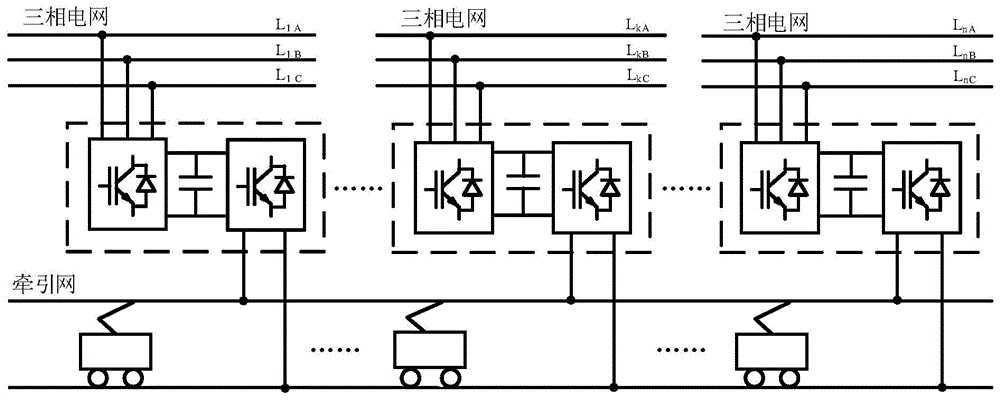
[0026] Figure 4 A through-type traction power supply system based on parallel connection of multi-level converters proposed by the present invention, each substation consists of an input step-down transformer connected to the three-phase power grid, and more than one parallel multi-voltage transformer connected to its output terminal. It consists of a power electronic conversion device for a flat three-phase-single-phase AC-DC-AC converter, and an output step-up transformer connecting the converter and the traction network. The substation is a controllable voltage source, and the traction networks of adjacent substations are directly connected to form a through traction power supply network, which outputs the AC voltage and current required by loads such as locomotives. Considering the long distance between substations and high reli...


PUM


Abstract

The invention discloses a continuous type traction power supply system based on multilevel converters connected in parallel. The continuous type traction power supply system is formed by connecting multiple continuous traction power supply substations in parallel and establishing networks. Traction networks of every two adjacent substations are directly connected, so that a continuous traction power supply network is formed. Each continuous traction power supply substation is composed of an input step-down transformer which is connected to a three-phase power grid, one or more multi-level three phase-single phase alternating current-direct current-alternating current converters which are connected in parallel and are connected with the output end of the input step-down transformer and an output boosting transformer connected with the converters and the traction network. By the adoption of the continuous type traction power supply system based on the multilevel converters connected in parallel, active power can be absorbed from the three-phase power grid and provided for the traction networks, and active power can also be absorbed from the traction networks and fed back to the three-phase power grid, each substation has the characteristic of a controllable voltage source, so that continuous traction network power supply to an electrified railway can be achieved, electricity phase splitting is thoroughly eliminated, and the electricity quality is greatly improved. Due to the fact that the structure that the multilevel converters are connected in parallel is arranged in each substation, the capacity is increased, and the reliability and the redundancy of the traction power supply system can be well improved.

Description

technical field [0001] The invention relates to the technical field of railway traction power supply systems, in particular to the field of traction network equipment without excessive phase intervals. Background technique [0002] The physical structure of the existing traction power supply system implements segmented power supply, which leads to the loss of speed and energy when the locomotive is over-phased, and the complex electrical transient process between the train and the network will seriously endanger the normal operation of main electrical equipment such as the traction network and trains. Work. There is a power supply dead zone in the traction network. Each power substation requires a set of traction transformers to work and a set for backup, which has poor reliability. There are few means to ensure reliability and the cost is high. In terms of electrical structure, there is a strong coupling electromagnetic relationship between the existing traction power supp...

Claims


Application Information

Patent Timeline
Patent Type & Authority Applications(China)
IPC IPC(8): B60M3/00H02M5/44
Inventor 何晓琼彭旭周瑛英
Owner SOUTHWEST JIAOTONG UNIV
Why Eureka
Try Eureka