Supercharge Your Innovation With Domain-Expert AI Agents!

Ground gas turbine using pulse knocking combustion

A pulse detonation, gas turbine technology, applied in gas turbine devices, deflagration combustion chambers, combustion chambers, etc., can solve the problems of complex combustion chamber structure, narrow combustion stability area, small air ratio, etc., and achieves low requirements for materials and cooling technology , The effect of short residence time and fast burning speed

Inactive Publication Date: 2014-09-10
HUANENG POWER INTERNATIONAL +1
View PDF7 Cites 14 Cited by
  • Summary
  • Abstract
  • Description
  • Claims
  • Application Information

AI Technical Summary

Problems solved by technology

[0005] The purpose of the present invention is to solve the problems existing in the existing ground gas turbines, such as the complex structure of the combustion chamber, the small proportion of air actually participating in the combustion, the narrow combustion stable area, the easy flameout and the need for frequent combustion adjustments, etc. The ground gas turbine used in the ground gas turbine has a simple structure, no cooling air film hole structure, and no complicated flame stabilizer; the combustion chamber does not need cooling air, and the compressed air can all participate in the combustion; the flame in the combustion chamber propagates at supersonic speed, no There are problems of combustion stability and flameout, and there is no need to conduct combustion adjustment tests on the combustion chamber, and the emission of combustion pollutants is low; in addition, the combustion process has the characteristics of self-pressurization, so it can reduce the number of stages of the compressor, reduce the power consumption of the compressor, and increase Power generation, improve cycle thermal efficiency

Method used


Image

  • Ground gas turbine using pulse knocking combustion
  • Ground gas turbine using pulse knocking combustion
  • Ground gas turbine using pulse knocking combustion

Examples


Embodiment Construction

[0028] The present invention will be further described below in conjunction with accompanying drawing.

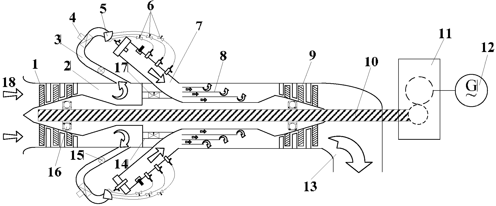
[0029] see figure 1 , a ground gas turbine using pulse detonation combustion in the present invention, comprising a compressor 1, a gas storage chamber 2, a plurality of gas supply pipelines 3, a plurality of pulse detonation combustion chambers 7, a pressure shaping chamber 8, a turbine 9, and a rotor 10 and tailpipe 13, and formed as figure 1 The flow path of the combustion gas passing through them indicated by the middle arrow, that is, the combustion gas flow path 18 .

[0030] Among them, the compressor 1 is arranged at the front end of the ground gas turbine, the gas outlet of the compressor 1 is connected with the gas storage chamber 2, the pressure shaping chamber 8, the turbine 9 and the tail nozzle 13 in sequence, and the rotor 10 is arranged between the compressor 1 and The center of the turbine 9 is connected to the compressor 1 and the turbine 9 respectively ...


PUM


Abstract

The invention discloses a ground gas turbine using pulse knocking combustion. The ground gas turbine comprises a gas compressor, a gas storage chamber, a plurality of gas supply pipelines, a plurality of pulse knocking combustion chambers, a pressure shaping chamber, a turbine, rotors and an exhaust nozzle, wherein the gas compressor is arranged at the most front end of the ground gas turbine; a gas outlet end of the gas compressor is connected with the gas storage chamber, the pressure shaping chamber, the turbine and the exhaust nozzle in sequence; the rotors are arranged in the centers of the gas compressor and the turbine, and are respectively connected with the gas compressor and the turbine through two bearings; one ends of the rotors are leaded out from the exhaust nozzle; the plurality of pulse knocking combustion chambers are arranged in the peripheral directions of the gas storage chamber and the pressure shaping chamber; an outlet of the gas storage chamber is respectively connected with inlets of the plurality of pulse knocking combustion chambers through the plurality of gas supply pipelines; outlets of the plurality of pulse knocking combustion chambers are respectively connected with an inlet of the pressure shaping chamber; and spark plugs and fuel pipelines are arranged in the peripheral directions of single pulse knocking combustion chambers. When the ground gas turbine is used, the leaded-out ends of the rotors are connected with a generator module through a transmission.

Description

【Technical field】 [0001] The invention relates to a gas turbine, in particular to a ground gas turbine utilizing pulse detonation combustion. 【Background technique】 [0002] All ground gas turbines use isobaric combustion to release fuel heat. Isobaric combustion is a kind of slow-burning combustion, and its flame propagation speed is relatively low, generally about a few meters to more than ten meters per second. The combustion chamber flame is easily blown out. In order to ensure the stability and reliability of the flame in the combustion chamber, it is generally necessary to carefully design the structure of the combustion chamber, using flame stabilizers such as swirlers, concave cavities, and sand dune vortexes to form a low-speed vortex area at the head of the combustion chamber, so that part of the burned high-temperature combustion products Generate backflow movement to form a continuous ignition source with automatic compensation ability to continuously ignite fre...

Claims


Application Information

Patent Timeline
IPC IPC(8): F02C5/00F23R7/00
Inventor 李晓丰肖俊峰高松王峰
Owner HUANENG POWER INTERNATIONAL
Features
  • R&D
  • Intellectual Property
  • Life Sciences
  • Materials
  • Tech Scout
  • Unparalleled Data Quality
  • Higher Quality Content
  • 60% Fewer Hallucinations
Learn More