Compensation method for perpendicularity error between feed shafts
A compensation method and verticality technology, which can be used in instruments, computer control, simulators, etc., and can solve problems such as long interpolation period.
- Summary
- Abstract
- Description
- Claims
- Application Information
AI Technical Summary
Problems solved by technology
Method used
Image
Examples
specific Embodiment approach 1
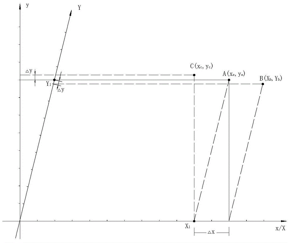
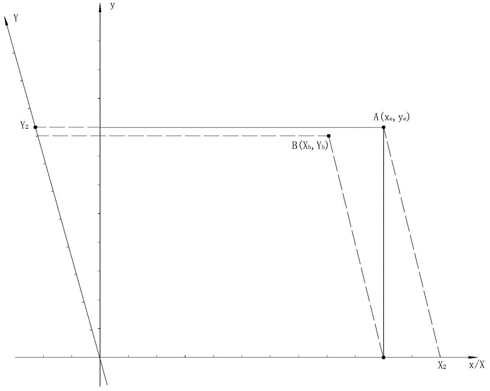
[0142] Specific Embodiment 1 Perpendicularity Error Compensation for Incremental Associated Data Streams
[0143] The data flow correlation control found that in the real-time control process of the tool path curve, L division, as the digital image of the tool path curve, is a geometric invariant in discrete motion. There is no coupling relationship between the L division and the T division. The L division determines the geometric characteristics of the tool path curve, and the T division determines the processing efficiency and quality.
[0144] Therefore, the planning process of L-division and T-division is a non-real-time process. The core task of the PC system is to plan the L division and T division of the tool path curve.
[0145] L division and T division only depend on the geometric characteristics of the tool path curve and the kinematics / dynamic characteristics of the feed axis, and have nothing to do with the interpolation period of the real-time operating system. ...
specific Embodiment approach 2
[0167] Specific Embodiment 2 Perpendicularity Error Compensation of Step-Type Associated Data Stream
[0168] Step-by-step associative data flow fully embodies the essence of digital control. In particular, in the real-time control of the tool path curve, the synchronization of the start point and the end point is the intrinsic property of the step-type associated data flow. For the step-type associated data flow, the relevant feed axis either feeds a feed equivalent or does not feed, and its discrete position information is in the form of "1" and "0".
[0169] Table 2
[0170]
[0171] Table 2 is a schematic diagram of the 2-dimensional step-by-step associated data flow of the toolpath curve in the orthogonal discrete coordinate system x / y, where the x-axis is the active axis and the y-axis is the linkage axis. The discrete scale is e, and the tool path curve is a function of x and y.
[0172] In Table 2, time T is discretized into n timing points: t i (i=1,...,n). Th...
specific Embodiment approach 3
[0216] Specific Implementation Mode 3 Perpendicularity Error Compensation of Existing CNC System
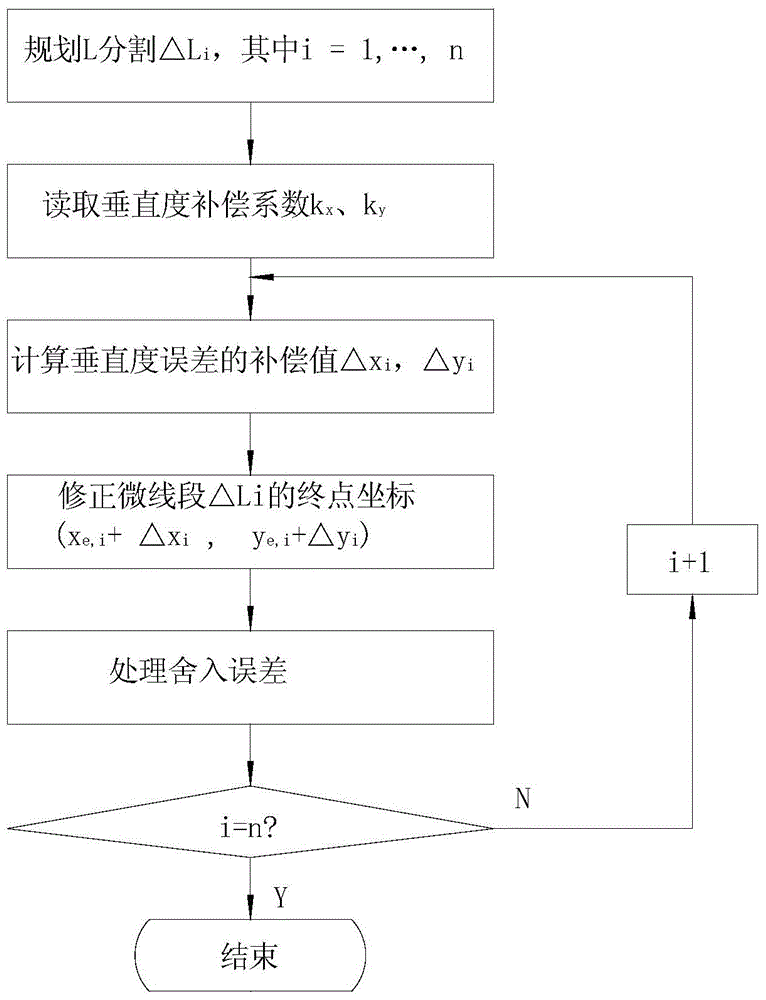
[0217] In the existing CNC system based on the IEEE definition, the usual orthogonal coordinate system x / y is used. Under the control of the real-time operating system, in an interpolation cycle T i Perform real-time interpolation within to obtain the micro-line segment △L i The end point coordinates of or the step-by-step associative data flow of the relevant feed axis. Obviously, if the interpolation cycle is long enough or the main frequency of the CPU is high enough, the micro-line segment △L i The X coordinate compensation value of the end point △x i Compensation value with Y coordinate △y i , and the generation of the stepwise associated data stream can be performed in one interpolation cycle T i processed in real time. In this case, the above two perpendicularity error compensation methods are applicable to existing CNC systems based on IEEE definitions.
[0218] Th...
PUM
 Abstract
Description
Claims
Application Information
 - R&D
- Intellectual Property
- Life Sciences
- Materials
- Tech Scout
- Unparalleled Data Quality
- Higher Quality Content
- 60% Fewer Hallucinations
Browse by: Latest US Patents, China's latest patents, Technical Efficacy Thesaurus, Application Domain, Technology Topic, Popular Technical Reports.
© 2025 PatSnap. All rights reserved.Legal|Privacy policy|Modern Slavery Act Transparency Statement|Sitemap|About US| Contact US: help@patsnap.com


