A Compensation Method for Perpendicularity Error Between Feed Axes
A compensation method and verticality technology, applied in instruments, computer control, simulators, etc., can solve the problem of long interpolation period, and achieve the effect of solving the compensation problem and solving the verticality error.
- Summary
- Abstract
- Description
- Claims
- Application Information
AI Technical Summary
Problems solved by technology
Method used
Image
Examples
specific Embodiment approach 1
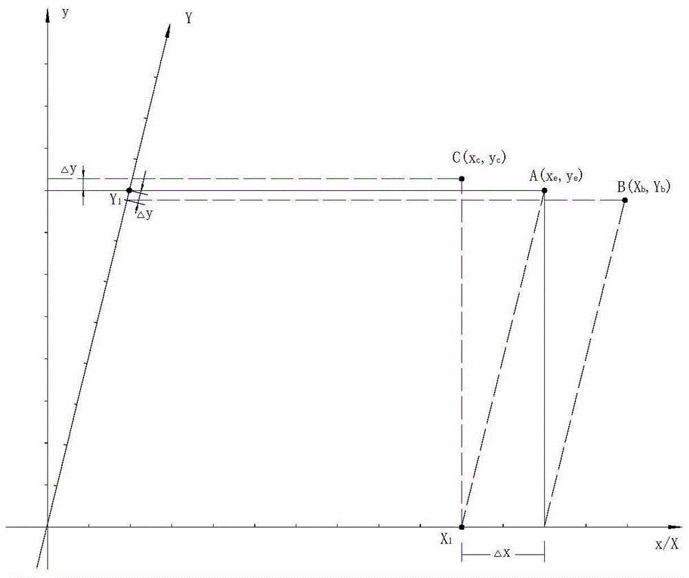
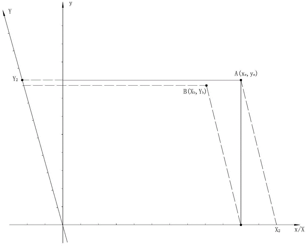
[0142] DETAILED DESCRIPTION - Perpendicularity Error Compensation for Incremental Associated Data Streams
[0143] The data flow correlation control found that in the real-time control process of the tool path curve, L division, as the digital image of the tool path curve, is a geometric invariant in discrete motion. There is no coupling relationship between the L division and the T division. The L division determines the geometric characteristics of the tool path curve, and the T division determines the processing efficiency and quality.
[0144] Therefore, the planning process of L-division and T-division is a non-real-time process. The core task of the PC system is to plan the L division and T division of the tool path curve.
[0145] L division and T division only depend on the geometric characteristics of the tool path curve and the kinematics / dynamic characteristics of the feed axis, and have nothing to do with the interpolation period of the real-time operating system....
specific Embodiment approach 2
[0167] DETAILED DESCRIPTION OF THE PREFERRED EMBODIMENTS Verticality Error Compensation for Two-Step Correlation Data Streams
[0168] Step-by-step associative data flow fully embodies the essence of digital control. In particular, in the real-time control of the tool path curve, the synchronization of the start point and the end point is the intrinsic property of the step-type associated data flow. For the step-type associated data flow, the relevant feed axis either feeds a feed equivalent or does not feed, and its discrete position information is in the form of "1" and "0".
[0169] Table 2
[0170]
[0171] Table 2 is a schematic diagram of the 2-dimensional step-by-step associated data flow of the toolpath curve in the orthogonal discrete coordinate system x / y, where the x-axis is the active axis and the y-axis is the linkage axis. The discrete scale is e, and the tool path curve is a function of x and y.
[0172] In Table 2, time T is discretized into n timing poin...
specific Embodiment approach 3
[0216] Specific Implementation Mode 3 Perpendicularity Error Compensation of Existing CNC System
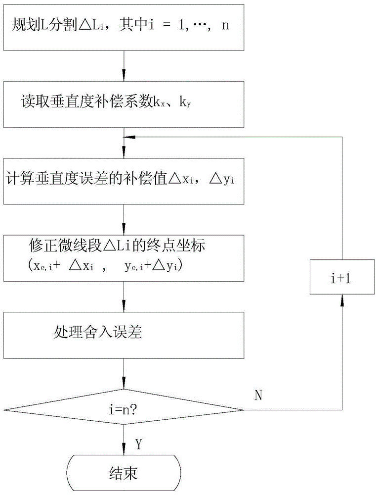
[0217] In the existing CNC system based on the IEEE definition, the usual orthogonal coordinate system x / y is used. Under the control of the real-time operating system, in an interpolation cycle T i Perform real-time interpolation within to obtain the micro-line segment △L i The end point coordinates of or the step-by-step associative data flow of the relevant feed axis. Obviously, if the interpolation cycle is long enough or the main frequency of the CPU is high enough, the micro-line segment △L i The X coordinate compensation value of the end point △x i Compensation value with Y coordinate △y i , and the generation of the stepwise associated data stream can be performed in one interpolation cycle T i processed in real time. In this case, the above two perpendicularity error compensation methods are applicable to existing CNC systems based on IEEE definitions.
[0218] Th...
PUM
 Abstract
Description
Claims
Application Information
 - R&D
- Intellectual Property
- Life Sciences
- Materials
- Tech Scout
- Unparalleled Data Quality
- Higher Quality Content
- 60% Fewer Hallucinations
Browse by: Latest US Patents, China's latest patents, Technical Efficacy Thesaurus, Application Domain, Technology Topic, Popular Technical Reports.
© 2025 PatSnap. All rights reserved.Legal|Privacy policy|Modern Slavery Act Transparency Statement|Sitemap|About US| Contact US: help@patsnap.com


