
A Reduction Reaction Shaft Furnace Waste Heat Recovery and Recycling System

A waste heat recovery and shaft furnace technology, applied in shaft furnaces, furnaces, waste heat treatment and other directions, can solve the problems of large heat energy waste and low waste heat recovery efficiency, and achieve the effects of high waste heat recovery and utilization efficiency, reduced emissions, and compact structure

Inactive Publication Date: 2016-03-02
JIANGSU UNIV
View PDF6 Cites 0 Cited by
  • Summary
  • Abstract
  • Description
  • Claims
  • Application Information

AI Technical Summary

Problems solved by technology

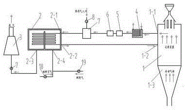
[0006] Aiming at many deficiencies such as low waste heat recovery efficiency and large waste of heat energy in the current shaft furnace direct reduction reaction process and waste heat recovery equipment, the present invention proposes a new reduction reaction shaft furnace waste heat recovery and recycling system, which comprehensively and efficiently utilizes shaft furnace exhaust High temperature reducing gas and waste heat of combustion gas

Method used


Image

  • A Reduction Reaction Shaft Furnace Waste Heat Recovery and Recycling System
  • A Reduction Reaction Shaft Furnace Waste Heat Recovery and Recycling System
  • A Reduction Reaction Shaft Furnace Waste Heat Recovery and Recycling System

Examples


Embodiment 1

[0022] like figure 1 As shown, a reduction reaction shaft furnace waste heat recovery and recycling system includes a shaft furnace 1, a reformer 2 and a waste gas discharge device 3, and the shaft furnace 1 is provided with a first exhaust port 1-1 and a reducing gas inlet 1 -2, the reformer 2 is provided with a raw material gas inlet 2-1 and a reducing gas outlet 2-2, and a first gas is sequentially connected between the exhaust port 1-1 and the raw material gas inlet 2-1 Water heat exchanger 4, scrubber 5, carbon dioxide absorption device 6 and the first mixing chamber 7, the first pressurizer 8 is arranged between the feed gas inlet and the first mixing chamber 7, used for feeding the feed gas To pressurize, the first mixing chamber 7 mixes the raw material gas and the exhaust gas in the shaft furnace 1 and then transfers it to the reformer 2; the reducing gas inlet 1-2 is connected to the raw material gas inlet 2-1; The reformer 2 is also provided with a first gas port 2...

Embodiment 2

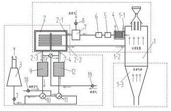
[0025] like figure 2 As shown, this embodiment is based on the technical solution of the first embodiment, and the following technical solution is added: between the first gas port 2-3 and the exhaust gas discharge device 3, a first regenerative heat exchanger is connected. Heater 9, a first reversing valve 10 is also provided between the first regenerative heat exchanger 9 and the exhaust gas discharge device 3; between the combustion air inlet and the second air port 2-4 A second reversing valve 11 and a second regenerative heat exchanger 12 are provided in sequence, and there is a pipeline communication between the first reversing valve 10, the second reversing valve 11 and the exhaust gas discharge device 3; A third reversing valve 13 is connected between the fuel gas inlet and the second gas port 2-4, and the third reversing valve 13, the first gas port 2-3 and the second gas port There is pipeline communication between 2-4.

[0026]The working process of this embodime...

Embodiment 3

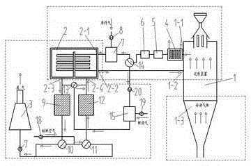
[0029] like image 3 As shown, this embodiment is based on the technical solution of the second embodiment, and the following technical solution is added: a fourth reversing valve 14 is also provided between the carbon dioxide absorption device 6 and the first mixing chamber 7, A second mixing chamber 15 is connected between the fourth reversing valve 14 and the fuel gas inlet, and a fifth pressurizer 20 is arranged between the fourth reversing valve 14 and the second mixing chamber 15 , the mixing chamber 15 mixes the gas passing through the reversing valve 14 with the fuel gas and then sends it to the reformer 2 .

[0030] The working process of this embodiment is: the pressurized combustion-supporting air and fuel gas are sent into the reformer 2 through the second gas port 2-4 for combustion to generate high temperature, and the raw material gas is passed into the reformer 2 for cracking reaction to generate High-temperature carbon monoxide and hydrogen (about 900 degrees...


PUM


Abstract

The invention relates to a system for recovering and recycling the waste heat of a reduction reaction vertical furnace. The system comprises a vertical furnace, a converting furnace and a waste gas emission device, wherein the vertical furnace is provided with a first exhaust port and a reducing gas inlet, the converting furnace is provided with a feed gas inlet and a reducing gas outlet, a first gas-water heat exchanger, a washer, a carbon dioxide absorption device and a first mixing chamber are sequentially connected between the exhaust port and the feed gas inlet, and a feed gas and an exhaust gas inside the vertical furnace are mixed by virtue of the first mixing chamber and then delivered into the converting furnace; the reducing gas inlet is connected with the feed gas inlet; the converting furnace is also provided with a first gas port and a second gas port, the first gas port is connected with the waste gas emission device, and a combustion-supporting air inlet and the fuel gas inlet are both communicated with the converting furnace by virtue of the second gas port. The system disclosed by the invention can be used for not only realizing the sufficient utilization of the parts of waste heat of the vertical furnace, but also recovering the carbon monoxide and the hydrogen which are not sufficiently combusted or subjected to reduction reaction, thereby enhancing the energy utilization rate, reducing the energy consumption, reducing the emission and achieving outstanding economic and social benefits.

Description

technical field [0001] The invention relates to a shaft furnace ironmaking waste heat recovery and recycling system, which belongs to the field of ironmaking technical facilities and equipment, and is used for the waste heat recovery and utilization of the shaft furnace direct reduction iron process. Background technique [0002] The development of direct reduced iron production is one of the important links for my country to get rid of the shortage of coking coal resources, change the energy structure of steel production, improve the quality and quality of steel products, solve the shortage of scrap steel resources, realize the comprehensive utilization of resources, and adhere to the sustainable development of the steel industry. Compared with other direct reduction processes, gas-based shaft furnace direct reduction technology has become the mainstream direct reduction process in the world due to its advantages of fast reduction speed, stable product quality, high degree o...

Claims


Application Information

Patent Timeline
Patent Type & Authority Patents(China)
IPC IPC(8): C21B13/02F27D17/00
CPCY02P10/25
Inventor 张西良冯延垒程晓农李伯全李亚波陈成
Owner JIANGSU UNIV
Learn More