
Diamond-coated tool

A technology of diamond and diamond layer, applied in the direction of manufacturing tools, metal processing equipment, metal material coating technology, etc., can solve problems such as wear or defect, and achieve the effect of improving tool life, oxidation resistance and defect resistance

Inactive Publication Date: 2014-09-17
SUMITOMO ELECTRIC HARDMETAL CORP
View PDF10 Cites 6 Cited by
  • Summary
  • Abstract
  • Description
  • Claims
  • Application Information

AI Technical Summary

Problems solved by technology

However, even when the cladding is made of diamond, wear or chipping may occur during machining depending on the workpiece or machining method

Method used


Image

  • Diamond-coated tool
  • Diamond-coated tool

Examples


Embodiment

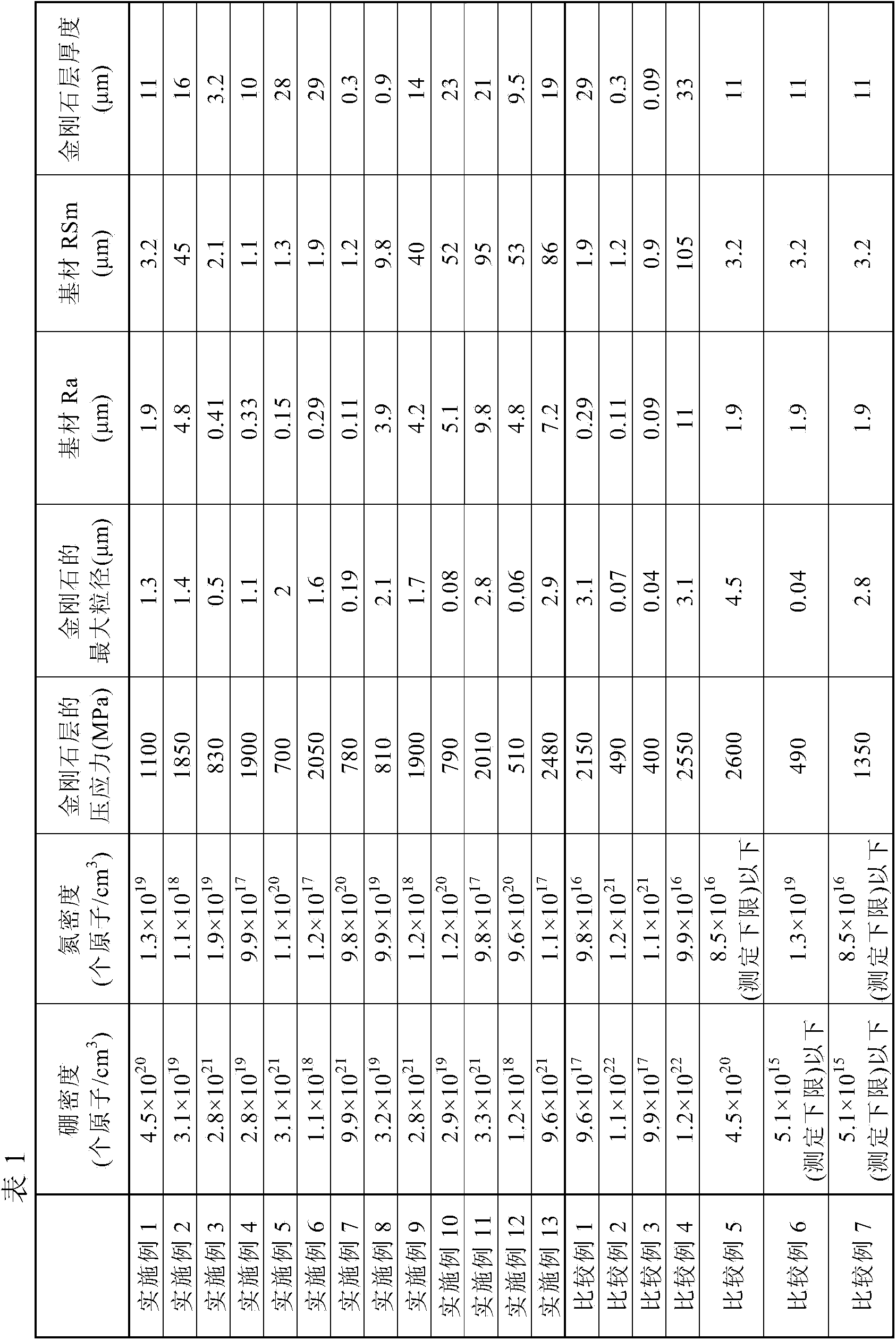
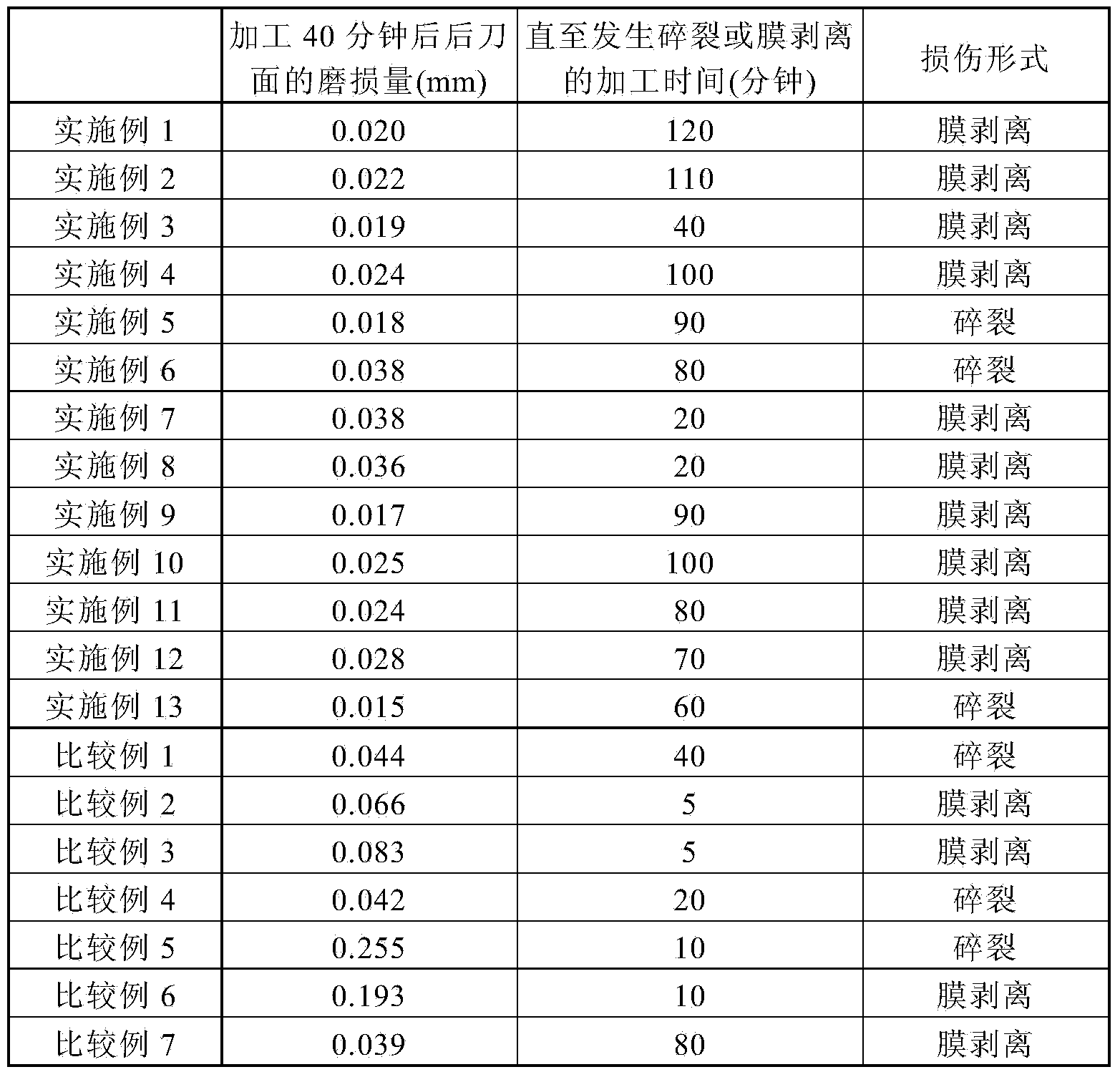
[0055] The present invention will be described in more detail with reference to Examples, which are not intended to limit the present invention.

[0056] Although the diamond layer is formed using a hot filament CVD method hereinafter, the diamond layer may be formed using a conventionally known CVD method such as microwave plasma CVD or plasma jet CVD.

[0057] In the manufacture of the diamond-coated tools of Examples and Comparative Examples, a material made of a material equivalent to JIS K10 type cemented carbide (WC-6% Co) and having a material equivalent to SPGN090308 (JIS B4120:1998) was used. Shaped blades serve as the base material for diamond-coated tools.

[0058] First, as the surface roughening treatment of the base material, the surface of the base material was blasted with various SiC fine powders (average particle diameter: 4 μm to 100 μm). The injection pressure is 0.15 MPa to 0.35 MPa, and the irradiation time is 10 seconds to 30 seconds. Subsequently, the...


PUM

PropertyMeasurementUnit
particle diameteraaaaaaaaaa
surface roughnessaaaaaaaaaa
thicknessaaaaaaaaaa

Abstract

A diamond coated tool according to the present invention includes a base material, and a diamond layer coating a surface of the base material, the diamond layer containing a diamond, 1.0 × 10 18 to 1.0 × 10 22 atoms / cm 3 of boron, and 1.0 × 10 17 to 1.0 × 10 21 atoms / cm 3 of nitrogen.

Description

technical field [0001] The present invention relates to a diamond coated tool in which the surface of a base material is coated with a diamond layer. Background technique [0002] Diamond has the highest hardness among existing substances, and has been used in cutting tools, grinding tools, wear-resistant tools, etc. for a long time in the form of natural diamonds and ultra-high pressure diamond sintered bodies. Since the establishment of the technology of manufacturing diamond films by chemical vapor deposition (CVD) in the 1980s, a relatively high degree of freedom in shape has been achieved, and technology development has been directed toward extending applications to complex curved surfaces such as drills and end mills. Advances in cutting tools and wear-resistant tools such as dies. In recent years, the demand has expanded to fiber-reinforced plastics (FRP), which are increasingly in demand in the aircraft industry, composite construction materials of FRP and metals su...

Claims


Application Information

Patent Timeline
Patent Type & Authority Applications(China)
IPC IPC(8): B23B27/14B23B27/20B23B51/00B23C5/16
CPCC23C16/271C23C16/277C23C16/0254Y10T407/27B23B27/20B23B51/00B23B2226/315B23B2228/10B23C5/16B23C2226/315B23C2228/10
Inventor 目黑贵一
Owner SUMITOMO ELECTRIC HARDMETAL CORP
Learn More