Novel energy-saving distillation technology of heat pump

A heat pump distillation and new process technology, applied in distillation separation, flash evaporation, fractionation and other directions, can solve the problems of insufficient heat recovery, high material grade requirements, compressor corrosion material grade requirements, etc., to reduce distillation energy consumption, improve The effect of energy efficiency

Active Publication Date: 2014-09-24
CHENGDU HUAXITANG ENVIRONMENTAL PROTECTION TECH CO LTD
View PDF4 Cites 3 Cited by
  • Summary
  • Abstract
  • Description
  • Claims
  • Application Information

AI Technical Summary

Problems solved by technology

[0005] 1. High investment, complex process flow, high-concentration toxic and harmful media are directly compressed by compressors, the compressors are severely corroded or require high material grades, and insufficient heat recovery;
[0006] 2. The compressed gas contains non-condensable gas, which leads to low heat transfer efficiency of the reboiler, high operating pressure of the reboiler, and easy corrosion;
The overhead gas of this process contains a high concentration of SO 2 , severe corrosion, or high requirements on material grades and complex processes
[0009] 2010101232510, titled "Heat Pump Flash Steam Stripping and Removal of Ammonia", and 2012101536708, titled "A Treatment Method for High-Concentration Ammonia-Containing Wastewater Based on Vapor Compression", both of which require the use of a reboiler, the process The process is complicated, and there are still problems that the compressor is in contact with high-concentration ammonia gas, severe corrosion, or high material grade requirements

Method used


Image

  • Novel energy-saving distillation technology of heat pump
  • Novel energy-saving distillation technology of heat pump
  • Novel energy-saving distillation technology of heat pump

Examples


Embodiment 1

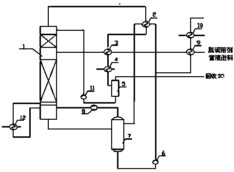
[0045] A. The still liquid at the bottom of the distillation tower is sent to the flash tower and flashed in the flash tower;

[0046] B. The flash steam generated by flash evaporation is sent into the compressor, and the compressor is used to compress the flash steam to do work;

[0047] C. Send the steam output from the compressor to the bottom of the distillation tower, and form the rising steam required for distillation with the vaporized pot liquid, and conduct mass transfer and heat transfer with the descending liquid at the upper part of the distillation tower to complete the distillation process;

[0048] The partially flashed still liquid exchanges heat with the steam discharged from the top of the distillation tower, and returns to the flash tower after recovering the steam heat; the remaining flashed still liquid exchanges heat with the feed liquid entering the distillation tower, and recovers the still After the liquid is heated, it is cooled by water and then sent...

Embodiment 2

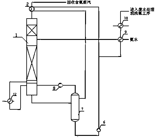
[0051] A. The still liquid at the bottom of the distillation tower is sent to the flash tower and flashed in the flash tower;

[0052] B. The flash steam generated by flash evaporation is sent into the compressor, and the compressor is used to compress the flash steam to do work;

[0053] C. Send the steam output from the compressor to the bottom of the distillation tower, and form the rising steam required for distillation with the vaporized pot liquid, and conduct mass transfer and heat transfer with the descending liquid at the upper part of the distillation tower to complete the distillation process;

[0054] The partially flashed still liquid exchanges heat with the steam discharged from the top of the distillation tower, and returns to the flash tower after recovering the steam heat; the remaining flashed still liquid exchanges heat with the feed liquid entering the distillation tower, and recovers the still After the liquid is heated, it is cooled by water and then sent...

Embodiment 3

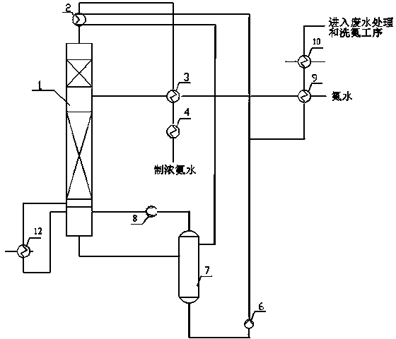
[0059] A. The still liquid at the bottom of the distillation tower is sent to the flash tower and flashed in the flash tower;

[0060] B. The flash steam generated by flash evaporation is sent into the compressor, and the compressor is used to compress the flash steam to do work;

[0061] C. Send the steam output from the compressor to the bottom of the distillation tower, and form the rising steam required for distillation with the vaporized pot liquid, and conduct mass transfer and heat transfer with the descending liquid at the upper part of the distillation tower to complete the distillation process;

[0062] The partially flashed still liquid exchanges heat with the steam discharged from the top of the distillation tower, and returns to the flash tower after recovering the steam heat; the remaining flashed still liquid exchanges heat with the feed liquid entering the distillation tower, and recovers the still After the liquid is heated, it is cooled by water and then sent...


PUM


Abstract

The invention provides a novel energy-saving distillation technology of a heat pump, aiming at reducing the device energy consumption of distillation of the heat pump and simplifying the process. The technology comprises the following steps: A. conveying a kettle solution at the bottom of a distillation column to a flash column, and performing flashing in the flash column; B. introducing flashing steam generated by flashing into a compressor, and carrying out compression on the flashing steam for acting by the compressor; C. introducing steam output by the compressor to the bottom in the distillation column, forming rising steam required for distillation by the steam output by the compressor and a vaporized kettle solution, and transferring mass and heat between the rising steam and a liquid declining from the upper part of the distillation column in a backflow mode to complete the distillation process; exchanging heat between partial kettle solution subjected to flashing with steam discharged from the top of the distillation column, and returning to the flash column after recycling heat of the steam; and exchanging heat of the residual kettle solution subjected to flashing with a material liquid entering the distillation column, and carrying out water cooling and recycling after recycling the heat of the kettle solution. The novel distillation technology provided by the invention is simple in technological process, low in investment and high in energy saving efficiency, and can save more than 70% of energy compared with a traditional distillation method.

Description

technical field [0001] The invention relates to the technical field of heat pump distillation, in particular to a new energy-saving process of heat pump distillation. Background technique [0002] The chemical industry is a large energy consumer, and distillation is a unit operation with extremely high energy consumption. However, the traditional distillation method has low thermodynamic efficiency and a lot of energy waste. For example, in the document "Application of Kangshifu Renewable Amine Desulfurization Technology" ("Sulfuric Acid Industry", 2007(1): 39-45), SO is separated from the desulfurization absorption liquid by distillation 2 , each ton of desulfurization liquid needs to consume 0.1-0.2t0.6MPa saturated water vapor; The ammonia in the ammonia water is separated by distillation, and the remaining ammonia water needs to consume -175Kg0.6MPa saturated water vapor per ton; "Analysis of Energy Consumption of Desulfurization Devices in Natural Gas Purification Plan...

Claims


Application Information

Patent Timeline
Patent Type & Authority Applications(China)
IPC IPC(8): B01D3/00B01D3/06B01D3/14
Inventor 任毅李东林
Owner CHENGDU HUAXITANG ENVIRONMENTAL PROTECTION TECH CO LTD
Why Eureka
Try Eureka