Afterburner oil supply device

A technology of afterburner and fuel supply device, applied in the direction of combustion chamber, continuous combustion chamber, combustion method, etc., can solve the problem of affecting the service life and safety of the engine, uneven distribution of atomized droplet diameter, and increasing the fuel cycle. The distribution range and other problems can be overcome to overcome the large inlet airflow velocity, reduce the length and improve the thrust-to-weight ratio.

Active Publication Date: 2014-09-24
XIAMEN UNIV
View PDF8 Cites 8 Cited by
  • Summary
  • Abstract
  • Description
  • Claims
  • Application Information

AI Technical Summary

Problems solved by technology

However, the high-speed injection of fuel to a concave surface to achieve atomization may lead to incomplete atomization process, with greater randomness, uneven distribution of atomized droplet diameter, and increased pollutant emissions; and using this met

Method used


Image

  • Afterburner oil supply device
  • Afterburner oil supply device
  • Afterburner oil supply device

Examples


Embodiment Construction

[0023] The preferred embodiments of the present invention will be described below in conjunction with the accompanying drawings, that is, the preferred embodiments described here are only used to illustrate and explain the present invention, and are not intended to limit the present invention.

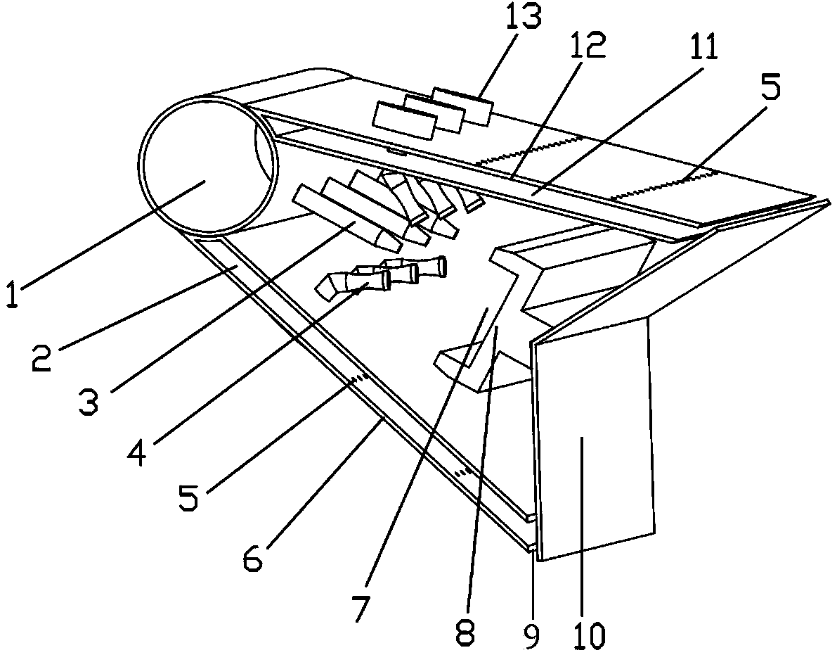
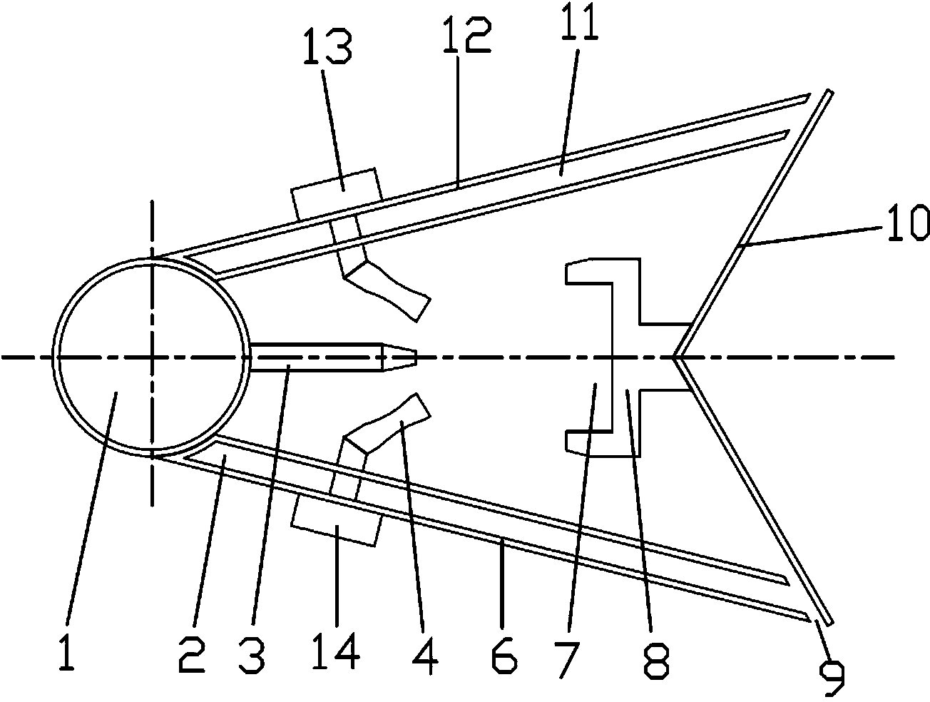
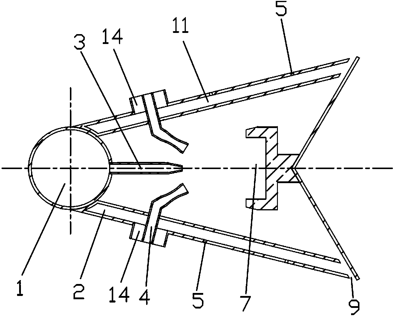
[0024] like Figure 1~4 As shown, the embodiment of the present invention is provided with a fuel supply pipe 1, an inner cooling chamber 2, a fuel nozzle 3, an air supply pipe 4, an inner wall surface 6, a resonant cavity 7, a resonant cavity body 8, a slot 9, a V-shaped baffle 10, Outer cooling cavity 11, outer wall surface 12, outer cooling cavity air inlet 13, inner cooling cavity air inlet 14.

[0025] The fuel supply pipe 1 is located at the head of the fuel supply device, and is in direct contact with the heat flow from the outlet of the low-pressure turbine of the aero-engine during operation. When the fuel flows in the fuel supply pipe 1, it can be preliminarily heated. The g...


PUM

PropertyMeasurementUnit
Angleaaaaaaaaaa

Abstract

The invention relates to an oil supply device, in particular to an afterburner oil supply device which comprises an oil supply pipe, an inner side cooling cavity, a fuel nozzle, gas supply pipes, an inner side wall, a resonant cavity, a resonant cavity body, slits, a V-shaped baffle, an outer side cooling cavity, an outer side wall, an outer side cooling cavity gas inlet and an inner side cooling cavity air inlet. The oil supply pipe is located on the head portion of the oil supply device, the gas supply pipes are located on the two sides of the oil supply device, and each of the two sides of the oil supply device is provided with three gas supply pipes which are evenly distributed. Fuel drips are sprayed out through the slits, cooling gas enters the outer side cooling cavity and the inner side cooling cavity through the outer side cooling cavity gas inlet and the inner side cooling cavity gas inlet respectively, the V-shaped baffle is mounted on the tail portion of the oil supply device, the inner side wall and the outer side wall are provided with cooling holes, and part of cooling gas in the inner side cooling cavity and the outer side cooling cavity is sprayed out from the cooling holes and forms cooling gas films on the surface of the inner side wall and the surface of the outer side wall. Fuel can be completely atomized, and emission of pollutants is reduced; the problems that airflow velocity is high and temperature is high at an inlet of an aero-engine afterburner are solved.

Description

technical field [0001] The invention relates to a fuel supply device, in particular to an atomized flame-stabilizing fuel supply device for an afterburner of an aero-engine. Background technique [0002] For fighter jets, in order to obtain altitude and speed advantages, expand the flight envelope, supersonic flight and other combat requirements on the battlefield, the engine is required to provide the maximum thrust in a short period of time to meet the work requirements of take-off, climbing, acceleration, and pursuit. The engine is required to increase thrust in a short time, so the concept of "afterburner" appeared. Generally speaking, the afterburner is located between the engine turbine and the tail nozzle. By re-injecting fuel and burning again, the total thrust can be increased by about 50% or even higher than the original maximum thrust in a short period of time. Afterburner Chambers have been widely used in active military aeroengines. Generally, the airflow velo...

Claims


Application Information

Patent Timeline
IPC IPC(8): F23R3/28
Inventor 邢菲阮灿徐磊磊方骁远邢盼
Owner XIAMEN UNIV
Why Eureka
Try Eureka