
Circulating dryer for cereals

A technology of cyclic drying and material circulation, applied in dryers, drying solid materials, drying gas layout, etc., can solve the problems of heat energy waste, inability to make full use of residual heat energy, and inability to dry grains with hot air, avoiding large air resistance, High thermal efficiency and improved uniformity

Active Publication Date: 2014-09-24
CHANGCHUN JIDA SCI INSTR EQUIP
View PDF6 Cites 5 Cited by
  • Summary
  • Abstract
  • Description
  • Claims
  • Application Information

AI Technical Summary

Problems solved by technology

[0006] After practice tests, the above-mentioned far-infrared drying device does not pass through the mesh plate and the grain layer well after the hot air generated by the oil furnace is mixed with the cold air in the hot and cold air mixing chamber, and then enters the infrared drying section through the hot air inlet. Most of them will go up along the gap between the mesh plate and the shell of the hot air drying section, so the grains cannot be dried well in the hot air drying section, and the cylinder type can not be fully utilized. There is a certain waste of heat energy in the residual heat energy discharged by the far-infrared radiator

Method used


Image

  • Circulating dryer for cereals
  • Circulating dryer for cereals
  • Circulating dryer for cereals

Examples


Embodiment 1

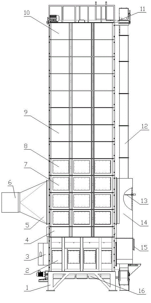
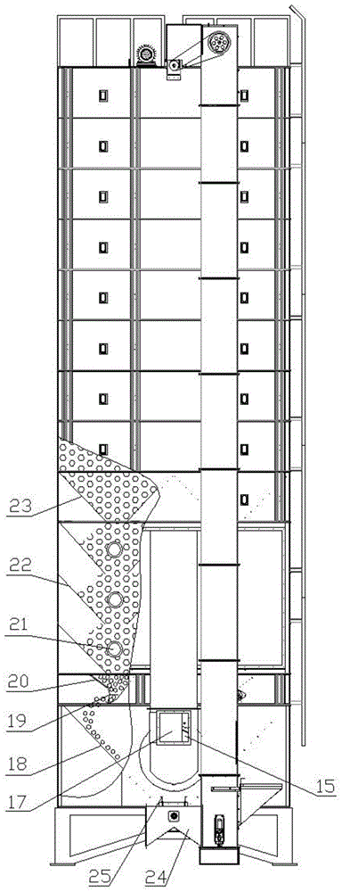
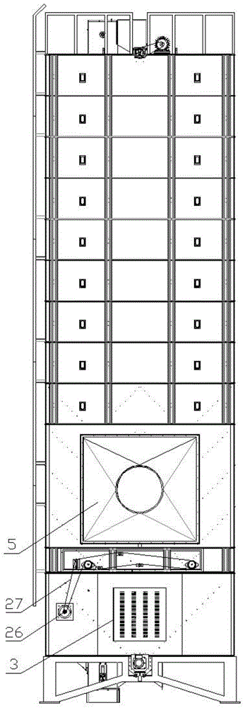
[0029] Such as figure 1 As shown, the grain circulation dryer includes a base 1 on which a radiation drying section 2, a grain discharge section 4, a hot air drying section 7 and a grain storage section are sequentially arranged from bottom to top. A material circulation conveying device is provided between the discharge port of the radiation drying section 2 and the feed port of the grain storage section. The grain storage section is formed by sequentially connecting the top grain storage section 10, the general grain storage section 9 and the bottom grain storage section 8 from top to bottom, and the general grain storage section 9 is formed by overlapping and connecting multiple sections. , the general grain storage section 9 in the present embodiment is formed by superposition of seven sections.

[0030] see figure 1 and figure 2 , the hot air drying section 7 is formed by overlapping and connecting multiple sections, and this embodiment takes three sections as an exam...

Embodiment 2

[0039] Such as Figure 1-Figure 3 As shown, the structure of this embodiment is basically the same as that of Embodiment 1, and the difference is that there is no infrared coating layer 29 on the outer surface of the tube of the radiator 28 in the radiation drying section 2, and all the other structures are the same as in Embodiment 1, and the dryer is only hot air to the grain. Convection dry.


PUM

PropertyMeasurementUnit
Thicknessaaaaaaaaaa

Abstract

The invention discloses a circulating dryer for cereals. The circulating dryer for cereals comprises a radiation drying section, a grain discharging section, a hot air drying section and a grain storing section, which are arranged on a base in sequence from the bottom up; a material circulating conveyer is arranged between the radiation drying section and the grain storing section; one side of the radiation drying section is communicated with a heat source that can produce a heat medium; an induced draft fan and an air mixing chamber are respectively arranged on two sides of the hot air drying section; the inlet of the air mixing chamber is communicated with a heat medium outlet of the radiation drying section; the outlet of the air mixing chamber is communicated with the induced draft fan through the hot air drying section. The circulating dryer has the advantages that not only can hot air drying be realized individually, but also hot air drying is organically combined with radiation drying, so that heat of the high-temperature heat medium is sufficiently used in high level and low level, the heat efficiency is high, the energy consumption is low, the drying is sufficient and uniform, the drying cost is low, the temperature is uniform, and the safety is good.

Description

technical field [0001] The invention relates to the technical field of grain drying, in particular to a novel grain circulation dryer. Background technique [0002] Drying is one of the most important processing stages in grain production. The so-called drying is the process of removing moisture from the material by means of heat supply, which is a complex heat and mass transfer process. In order to ensure the good quality of grain in drying operation, appropriate drying conditions and equipment must be selected to minimize the adverse effects of drying on grain quality. [0003] At present, the normal-pressure hot air drying using hot air as the medium for convective heat transfer is still the most widely used and most economical grain dehydration storage method, such as cross-flow grain dryers. The grain channel of the cross-flow grain dryer is a vertical grain channel made of two layers of vertical nets. The grain forms a layer of grain wall in the channel, and the grai...

Claims


Application Information

Patent Timeline
IPC IPC(8): F26B17/12F26B23/00F26B21/00F26B25/00A23B9/08
CPCY02P60/85
Inventor 吴文福张亚秋韩峰刘春山刘哲吴玉柱
Owner CHANGCHUN JIDA SCI INSTR EQUIP
Learn More