Micro mechanical differential capacitive pressure gauge

A technology of differential capacitance and pressure gauge, which is applied in the direction of fluid pressure measurement, circuit, and force measurement using capacitance changes, and can solve the problems of difficult implementation process and few differential capacitance pressure gauges.

Inactive Publication Date: 2014-09-24
PEKING UNIV
View PDF6 Cites 8 Cited by
  • Summary
  • Abstract
  • Description
  • Claims
  • Application Information

AI Technical Summary

Problems solved by technology

[0018] In 2003, Dae-Sung Lee of South Korea published a patent US6,651,506 B2, which introduced two possible structures of a differential capacitive pressure gauge. The capacitive pressure sensor can realize differential detection of pressure, but realizes There are still some difficulties in the process
[0020] At present, there are few research results on differential capacitance manometers, mainly the combination of variable capacitance and reference capacitance to detect differential pressure, or some achievements only in structural design, simple process, strict differential capacitance manometer There are very few reports

Method used


Image

  • Micro mechanical differential capacitive pressure gauge
  • Micro mechanical differential capacitive pressure gauge
  • Micro mechanical differential capacitive pressure gauge

Examples


Embodiment Construction

[0036] In order to make the above-mentioned structures, features and advantages of the present invention more obvious and understandable, the present invention will be further described in detail below in conjunction with the accompanying drawings and specific embodiments.

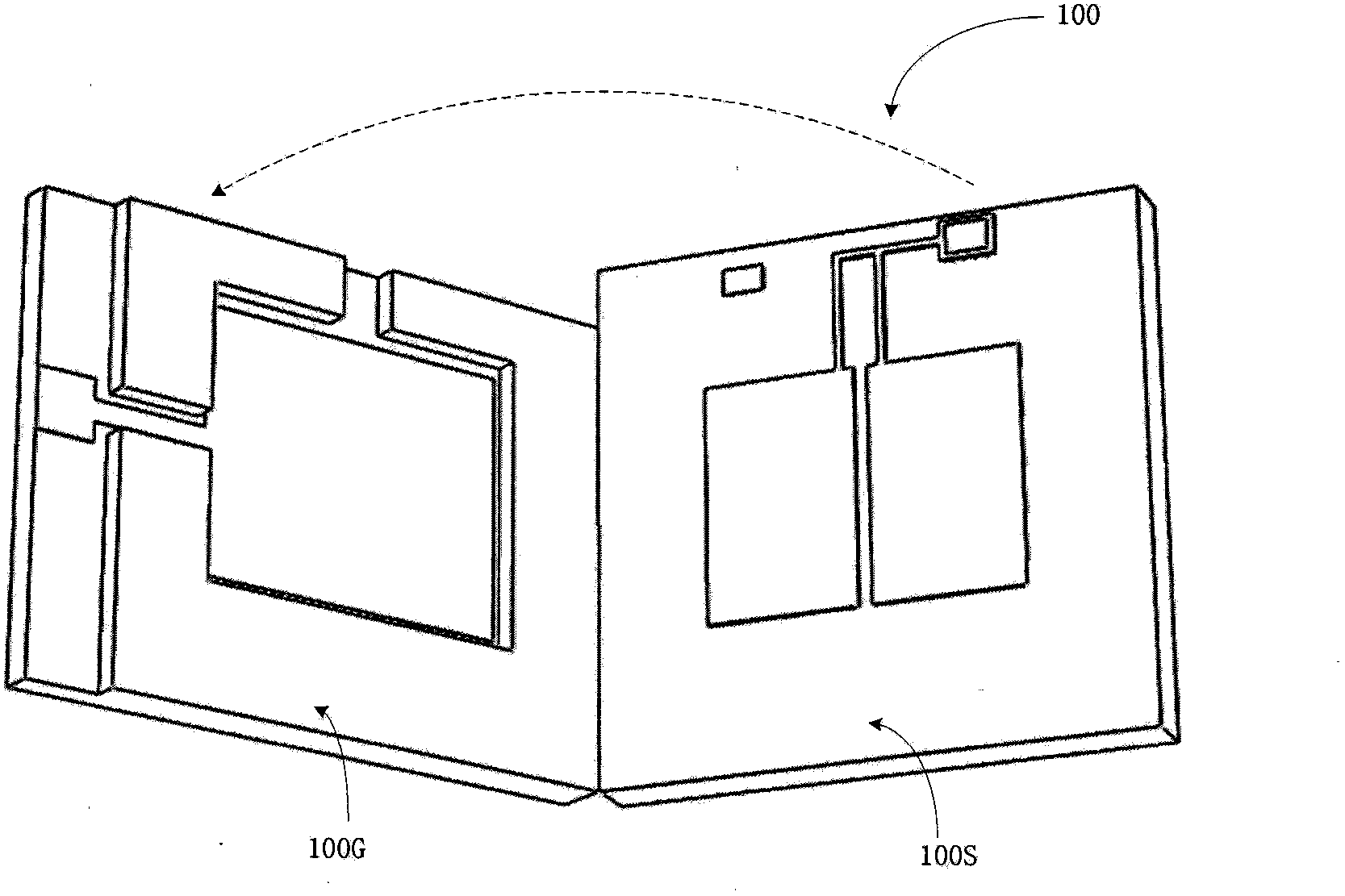
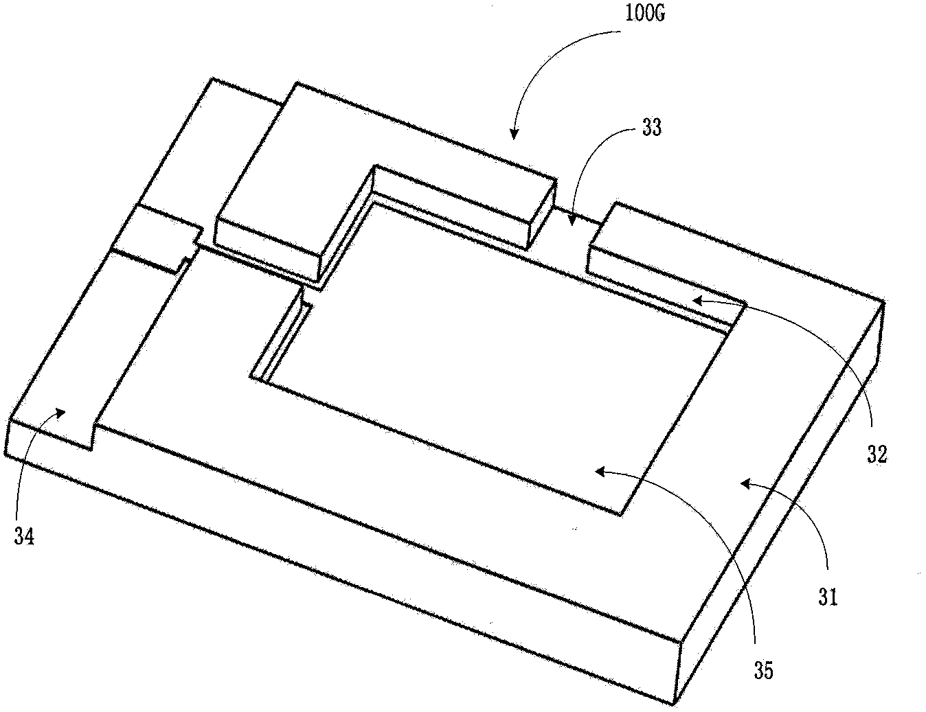
[0037] figure 1 It is a structural schematic diagram of a micromechanical differential capacitive manometer of the present invention, 100G is the upper electrode cover plate of the manometer, and 100S is the lower silicon wafer; figure 2 for figure 1 In the structural schematic diagram of the upper plate 100G, a groove 32 is etched on the glass or silicon wafer 31 by photolithography. The groove 32 is used for subsequent metal deposition to form the upper electrode plate and the bonding electrode. The groove The function of 33 is to reserve a space for bonding the cantilever beam on the lower silicon wafer 100S, and the groove 34 is a scribe groove reserved for dicing.

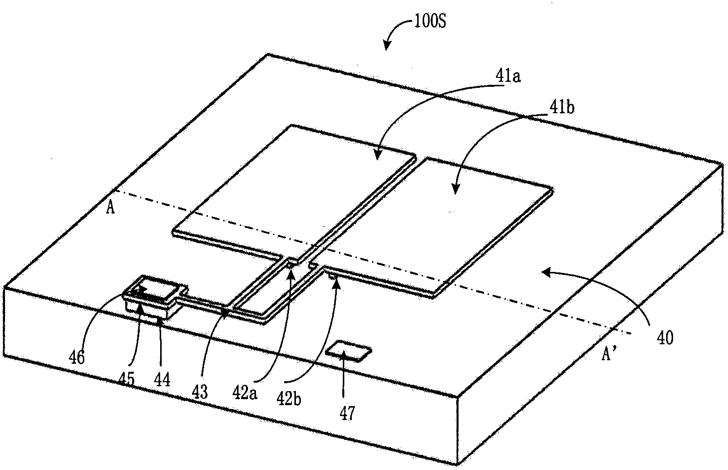
[0038]The structure of the lower...


PUM

PropertyMeasurementUnit
areaaaaaaaaaaa

Abstract

The invention discloses a micro mechanical differential capacitive pressure gauge. Two capacitors of the pressure gauge are formed by three capacitive polar plates: an upper polar plate formed through depositing a metal on a glass sheet or a silicon wafer; a lower polar plate formed by heavily doped silicon and an intermediate movable polar plate which is partly connected with a pressure-sensitive membrane and formed by monocrystal silicon or polycrystalline silicon. The pressure gauge is based on a basic silicon cup structure in a pressure gauge structure, when a pressure is applied to the sensitive membrane, the membrane is deformed and the intermediate polar plate connected with the sensitive membrane is also deformed so that the capacitances of the upper and lower capacitors are changed and thus differential signal output is formed. The preparation process of the pressure gauge is simple and advantages of a differential structure can be used to realize differential detection of pressure.

Description

technical field [0001] The invention relates to the technical field of MEMS (micro-electro-mechanical systems) differential capacitive pressure gauges. Background technique [0002] Capacitive structures are widely used in the field of microsensors. Compared with piezoresistive structures, capacitive structures have lower temperature coefficients. Capacitive structures have the advantages of low power consumption, high sensitivity, simple structure, and good dynamic characteristics. , so the capacitive sensor is considered to be a promising sensor. However, due to the nonlinearity of the capacitive sensor itself, the detection of tiny capacitance is susceptible to the influence of parasitic capacitance and the interference of the environmental electromagnetic field. The capacitive sensor did not make great progress until the 1980s. The first silicon capacitive pressure sensor was reported by Ford Motor in 1979. Since then, many companies, universities and scientific researc...

Claims


Application Information

Patent Timeline
Patent Type & Authority Applications(China)
IPC IPC(8): G01L1/14G01L9/12B81B7/00
Inventor 杨琛琛高成臣张扬熙
Owner PEKING UNIV
Why Eureka
Try Eureka