
Continuous lateral blowing tin smelting device

A technology of tin smelting and tin liquid, which is applied in the field of continuous side-blowing tin smelting equipment, can solve the problems of high maintenance cost, low production efficiency, complicated operation, etc., and achieve the effects of good sealing performance, high environmental protection, and simplified process

Active Publication Date: 2014-10-01
CHINA ENFI ENGINEERING CORPORATION
View PDF4 Cites 8 Cited by
  • Summary
  • Abstract
  • Description
  • Claims
  • Application Information

AI Technical Summary

Problems solved by technology

The short kiln smelting process has long been eliminated due to high investment, management and maintenance costs, large flue gas volume, and low direct recovery rate
The equipment structure of Kaldor furnace is complicated, the maintenance cost is high, the furnace life is short, and the refractory material consumption is large
Reverberatory furnaces are rapidly being replaced by enhanced smelting methods due to their shortcomings such as low production efficiency, low thermal efficiency, high fuel consumption, and high labor intensity.
Disadvantages of electric furnace tin smelting are too high power consumption, which is only suitable for processing low-iron materials; blast furnace smelting process requires materials to be granulated or pelletized, expensive metallurgical coke is consumed, the atmosphere in the furnace is difficult to control, and the disadvantages of high volatilization rate of tin are no longer available. reuse
Ausmelt smelting is an enhanced melting pool smelting technology. It is operated in stages, and the tin content in slag can be reduced to a lower level, but the investment is large, the maintenance cost is high, and the operation is complicated.

Method used


Image

  • Continuous lateral blowing tin smelting device
  • Continuous lateral blowing tin smelting device

Examples


Embodiment Construction

[0021] Embodiments of the present invention are described in detail below, examples of which are shown in the drawings, wherein the same or similar reference numerals designate the same or similar elements or elements having the same or similar functions throughout. The embodiments described below by referring to the figures are exemplary and are intended to explain the present invention and should not be construed as limiting the present invention.

[0022] In the field of metallurgical technology, the difference between top blowing and side blowing is not only a change in the position of the spray gun, but also a completely different smelting equipment and process. For example, in the field of steelmaking technology, bottom-blowing steelmaking was initially used, but the later development of top-blowing steelmaking is a pioneering invention, which is a completely different technology from bottom-blowing. It is not simply changing the spray gun from bottom-blowing to It is to...


PUM


Abstract

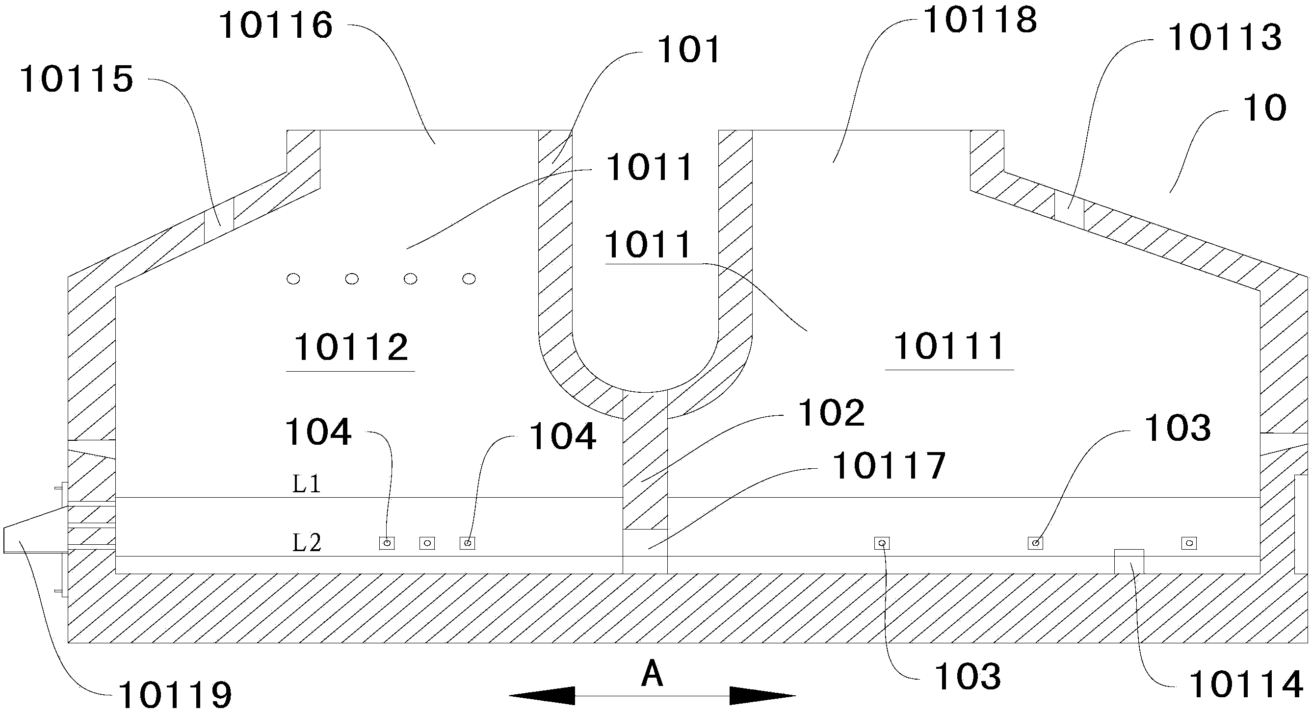
The invention relates to a continuous lateral blowing tin smelting device, comprising a reacting furnace, a lateral blowing spray gun of a smelting zone, and a lateral blowing spray gun of a reducing zone, wherein a furnace chamber is formed inside the reacting furnace; a molten pool for containing slag and tin liquor is arranged at the lower part of the furnace chamber; a partition wall is arranged inside the furnace chamber and extends into the molten pool, so as to divide the furnace chamber into a smelting zone and a reducing zone; the molten pool in the smelting zone is communicated with the molten pool in the reducing zone; a charge door and a tin discharge hole are formed in the wall of the smelting zone; a reducing agent inlet and a slag discharge hole are formed in the wall of the reducing zone; a smoke outlet communicated with each of the smelting zone and the reducing zone is formed in the top wall of the furnace chamber; the lateral blowing spray gun of the smelting zone is arranged on the lateral wall of the smelting zone; the lateral blowing spray gun of the reducing zone is arranged on the lateral wall of the reducing zone. The continuous lateral blowing tin smelting device has the advantages of low energy consumption, good sealing property, high environmental protection property, simple structure, easy operation and the like.

Description

technical field [0001] The invention relates to a continuous side blowing tin smelting device. Background technique [0002] Tin smelting technologies include tin concentrate reverberatory furnace smelting process, electric furnace smelting process, Ausmelt smelting process, blast furnace smelting process, short kiln smelting process, and Kaldor furnace tin smelting process. The short kiln smelting process has long been eliminated due to high investment, management and maintenance costs, large flue gas volume, and low direct recovery rate. The equipment structure of the Kaldor furnace is complex, the maintenance cost is high, the furnace life is short, and the consumption of refractory materials is large. Reverberatory furnaces are rapidly being replaced by enhanced smelting methods due to their shortcomings such as low production efficiency, low thermal efficiency, high fuel consumption, and high labor intensity. Disadvantages of electric furnace tin smelting are too high...

Claims


Application Information

Patent Timeline
IPC IPC(8): C22B25/02
Inventor 李东波黎敏王忠实张振民胡丕成许良冯双杰姚霞曹珂菲邓兆磊陈学刚陈霞
Owner CHINA ENFI ENGINEERING CORPORATION
Learn More