
Thermo-acoustic three-phase alternating current generating system driven by double-temperature-position heat source

A three-phase AC and power generation system technology, applied in the direction of mechanisms, electrical components, electromechanical devices that generate mechanical power, etc., can solve the problems of many intermediate links, low conversion efficiency, environmental pollution, etc. Low, high utilization effect

Inactive Publication Date: 2014-10-01
ZHEJIANG UNIV
View PDF6 Cites 8 Cited by
  • Summary
  • Abstract
  • Description
  • Claims
  • Application Information

AI Technical Summary

Problems solved by technology

Thermal power generation still occupies a considerable proportion in today's electricity production, but because thermal power generation needs to be converted by burning fossil fuels first, there are many intermediate links, the conversion efficiency is low, and a large amount of harmful gases are emitted during the process, causing environmental pollution
There are many high-temperature processes in industrial enterprises, and a large amount of waste heat remains after the production process is completed. These waste heat cannot be effectively used, which is low-grade energy.

Method used


Image

  • Thermo-acoustic three-phase alternating current generating system driven by double-temperature-position heat source
  • Thermo-acoustic three-phase alternating current generating system driven by double-temperature-position heat source
  • Thermo-acoustic three-phase alternating current generating system driven by double-temperature-position heat source

Examples


Embodiment Construction

[0046] The present invention will be further described below in conjunction with specific examples.

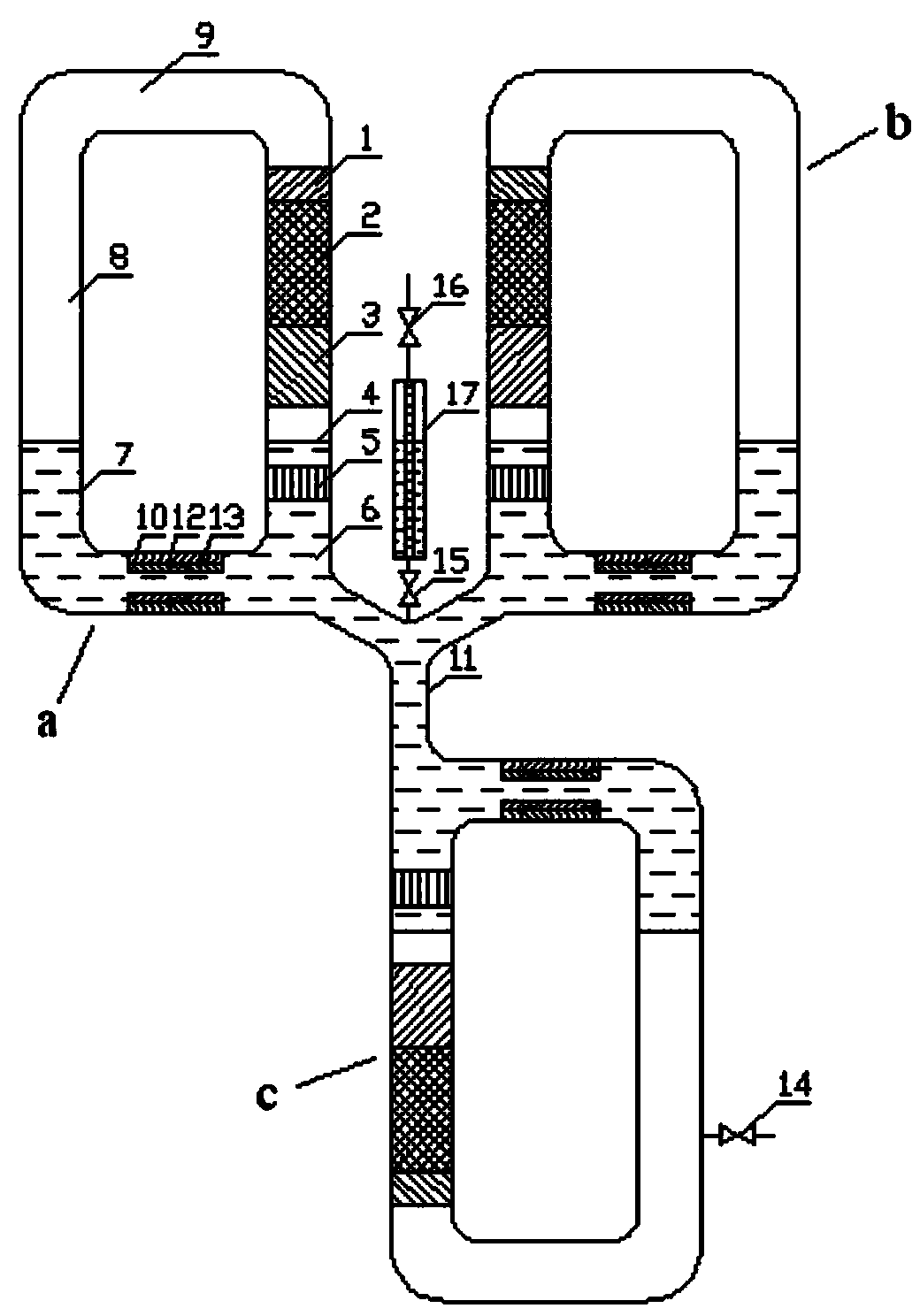
[0047] Such as figure 1 As shown, the thermoacoustic three-phase AC power generation system driven by a dual-temperature heat source includes three loop units with the same structure, which are loop unit a, loop unit b, and loop unit c. Each loop unit includes a heat Acoustic conversion device and magnetic fluid power generation device.

[0048] The thermoacoustic conversion device includes a high-temperature heat exchanger 1 , a regenerator 2 , a medium-temperature heat exchanger 3 , a liquid buffer pipe 4 , a room temperature heat exchanger 5 , a U-shaped pipe 7 , a feedback pipe 8 and an acoustic volume chamber 9 connected end to end. Wherein the high temperature heat exchanger 1, the regenerator 2, the medium temperature heat exchanger 3, the liquid buffer pipe 4 and the room temperature heat exchanger 5 are sequentially connected from top to bottom, and the U-shaped pipe...


PUM


Abstract

The invention discloses a thermo-acoustic three-phase alternating current generating system driven by a double-temperature-position heat source. The thermo-acoustic three-phase alternating current generating system comprises a magnetic fluid electric generating device and a thermo-acoustic converting device forming a loop. The loop is filled with a phase-changeable work medium, the liquid phase of the phase-changeable work medium serves as the work medium of the magnetic fluid electric generating device, and the gas phase of the phase-changeable work medium serves as the medium of the thermo-acoustic converting device. The magnetic fluid electric generating device and the matched thermo-acoustic converting device serve as a loop unit, the thermo-acoustic three-phase alternating current generating system at least comprises two loop units, and the loop units are communicated with each other to share the phase-changeable work medium. A certain amount of acoustic power is produced through a gas-liquid phase change thermo-acoustic converting mechanism, and a traveling wave thermo-acoustic engine serves as an amplification stage to amplify the produced acoustic power. A medium temperature heat exchanger and a high temperature heat exchanger are different in heating temperature, the double-temperature-position heat source can be used for driving the system to work, and the utilization rate of a medium and low temperature position and low grade heat source can be increased. Gas-liquid phase change exists in the system, and therefore the self-adaptation adjusting capacity is achieved.

Description

technical field [0001] The invention relates to a power generation system, in particular to a thermoacoustic three-phase AC power generation system driven by a dual-temperature-position heat source. Background technique [0002] The thermoacoustic engine has been a research hotspot in recent years due to its characteristics of no mechanical moving parts, simple structure, reliable operation and long life. The prototype of traveling wave thermoacoustic engine appeared as early as more than 200 years ago, but due to the low acoustic reactance at the regenerator and the high working vibration velocity, serious viscous loss was caused, which limited the engine efficiency. The performance of the thermoacoustic Stirling engine proposed by Backhaus and Swift of the North Alamos National Laboratory in the United States has been significantly improved, but the resonant tube of the standing wave is still the main part, and its size is usually large. The dimension is about 4m-10m, and...

Claims


Application Information

Patent Timeline
Patent Type & Authority Applications(China)
IPC IPC(8): H02K44/08H02K44/16H02K44/24F03G7/00
Inventor 汤珂封叶金滔吴云翔黄迦乐
Owner ZHEJIANG UNIV
Learn More