
A heat storage heat exchanger and a heat storage heat exchange device

A technology for heat storage heat exchangers and heat exchange devices, which is applied in the types of heat exchangers, indirect heat exchangers, heat storage equipment, etc., and can solve problems such as failure to improve comprehensive energy saving effects, difficult maintenance, and uneven fluid distribution , to achieve the effect of good heat transfer and flow comprehensive performance, good use effect, and fast heat storage and discharge speed

Active Publication Date: 2016-04-13
SOUTH CHINA UNIV OF TECH
View PDF6 Cites 0 Cited by
  • Summary
  • Abstract
  • Description
  • Claims
  • Application Information

AI Technical Summary

Problems solved by technology

Traditional heat storage heat exchangers generally use a single heat storage medium, that is, a single structured heat storage medium or a single scattered heat storage medium, but the use of these two heat storage media alone has its own shortcomings, such as a single The heat medium has the disadvantages of easy clogging, difficult maintenance, and high manufacturing cost. A single scattered heat storage medium has the problems of uneven fluid distribution and small specific surface area. Therefore, the traditional heat storage heat exchanger cannot play a good role in heat storage and exchange. The heat storage and release performance of the heater, the secondary energy cannot be fully recycled, and the comprehensive energy saving effect cannot be improved

Method used


Image

  • A heat storage heat exchanger and a heat storage heat exchange device
  • A heat storage heat exchanger and a heat storage heat exchange device
  • A heat storage heat exchanger and a heat storage heat exchange device

Examples


Embodiment 1

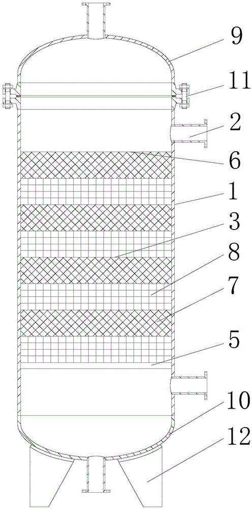
[0029] A heat storage heat exchanger, comprising a tank body 1, the upper and lower sides of the tank body 1 are respectively provided with gas inlet and outlet conduits 2, and a heat storage bed 3 and a heat storage bed fixing structure are arranged between the upper and lower gas inlet and outlet conduits in the tank body 1 The heat storage bed 3 is fixed in the tank body 1 through the heat storage bed fixing structure. Specifically, the heat storage bed fixing structure includes a heat storage medium support plate 5 and a heat storage medium pressure ring 6. The heat storage bed 3 is arranged on the Between the heat medium support plate 5 and the heat storage medium pressure ring 6 .

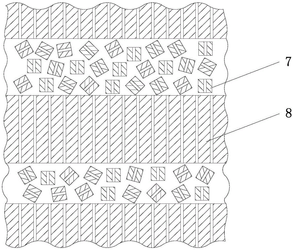
[0030] The heat storage bed 3 includes a stacked scattered heat storage medium layer 7 and a regular heat storage medium layer 8. The scattered heat storage medium layer 7 is stacked together by a plurality of scattered heat storage media. A first flow channel is formed between the media, and...

Embodiment 2

[0036] A heat storage and heat exchange device, including a heat storage heat exchanger of the first two embodiments, an intelligent controller 14, a hot gas pipeline 15, and an air pipeline 16. The gas inlet and outlet conduits 2 include hot gas inlet and outlet and air The inlet and outlet, the inlet and outlet of hot air and the inlet and outlet of air are respectively provided with valves. Specifically, the valves are pneumatic valves. The inlet and outlet of hot air include a hot air inlet 21 and a hot air outlet 22. On the body 1, the air inlet and outlet include an air inlet 23 and an air outlet 24, and the air inlet 23 and the air outlet 24 are respectively arranged on the tank body 1 up and down. The hot gas inlet 21 , the hot gas outlet 22 , the air inlet 23 and the air outlet 24 are provided with the pneumatic valves. The output port of the hot gas pipeline 15 is provided with a hot gas outlet temperature sensor 25, the output port of the air pipeline 16 is provided...

Embodiment 3

[0045] This embodiment is controlled by setting the alternate heat storage and heat release time of the two heat storage heat exchangers, the details are as follows: the regular heat storage medium layer uses a honeycomb ceramic heat storage body, and its specification is Φ4mm honeycomb round holes, and the heat storage is scattered The medium layer uses thick-walled ceramic Pall rings with a specification of Φ16x16x5mm. The two selected heat storage media are alternately stacked in the tank. The height of a single regular heat storage medium layer is 40mm, and the height of a single scattered heat storage medium layer is 60mm, the regular heat storage medium layer and the random heat storage medium layer are 5 layers each. Both tanks have a diameter of 500mm and a height of 1200mm. The valve switching time is set to 1min through the intelligent controller, that is, the alternate heat storage and heat release process of the two heat storage heat exchangers is 1min, and the flo...


PUM


Abstract

The invention discloses a regenerative heat exchanger which comprises a tank body, a gas inlet conduit and a gas outlet conduit are respectively arranged at the upper part and the lower part the tank body, heat accumulation beds and heat accumulation bed fixing structures are also arranged in the tank body, the heat accumulation beds are fixedly arranged in the tank body through the heat accumulation bed fixing structures and comprise randomly-stacked heat accumulation medium layers and regularly-put heat accumulation medium layers which are superposed together, the randomly-stacked heat accumulation medium layers are formed by stacking a plurality of randomly-stacked heat accumulation mediums, a first flow channel is formed among the randomly-stacked heat accumulation mediums, each randomly-stacked heat accumulation medium is provided with a second flow channel, the first flow channel and the second flow channel among the randomly-stacked heat accumulation mediums form a bent irregular flow channel, a regular flow channel is formed among the regularly-put heat accumulation medium layers, and the irregular flow channel is partially or fully communicated with the regular flow channel. The regenerative heat exchanger has the advantages of high heat accumulation and release speed, good heat transfer and comprehensive flow property, continuous heat exchange, energy conservation, environment friendless and the like, and can be used for treating a plurality of high-temperature waste gases produced in the industrial production process, and the requirements on energy conservation and emission reduction are met.

Description

technical field [0001] The invention relates to a device for recovering and utilizing waste gas heat, in particular to a heat storage heat exchanger and a heat storage heat exchange device. Background technique [0002] At present, part of the equipment used for waste gas treatment in metallurgy, electric power, petroleum, chemical and other industries is a heat storage heat exchanger, which realizes short-term storage of energy through a heat storage medium, and recovers the waste heat in the waste gas for preheating cold air. The heat storage medium is an important part of the heat storage heat exchanger, which can be divided into many types. There are two types of heat storage media commonly used in industrial production: random heat storage media and structured heat storage media. Traditional heat storage heat exchangers generally use a single heat storage medium, that is, a single structured heat storage medium or a single scattered heat storage medium, but the use of ...

Claims


Application Information

Patent Timeline
Patent Type & Authority Patents(China)
IPC IPC(8): F28D20/00F23L15/00
CPCY02E20/34Y02E60/14
Inventor 冯毅田丽军
Owner SOUTH CHINA UNIV OF TECH
Learn More