Demodulation circuit used for passive ultrahigh frequency RFID label chip

An RFID tag and demodulation circuit technology, applied in the field of radio frequency identification, can solve the problems of low input range, high power consumption, and poor tag chip sensitivity, and achieve the effects of poor sensitivity, reduced power consumption, and low bit error rate.

Active Publication Date: 2014-10-08
HUAZHONG UNIV OF SCI & TECH
View PDF4 Cites 13 Cited by
  • Summary
  • Abstract
  • Description
  • Claims
  • Application Information

AI Technical Summary

Problems solved by technology

[0004] In view of the defects of the prior art, the purpose of the present invention is to provide a demodulation circuit for pass

Method used


Image

  • Demodulation circuit used for passive ultrahigh frequency RFID label chip
  • Demodulation circuit used for passive ultrahigh frequency RFID label chip
  • Demodulation circuit used for passive ultrahigh frequency RFID label chip

Examples


Embodiment Construction

[0023] In order to make the object, technical solution and advantages of the present invention clearer, the present invention will be further described in detail below in conjunction with the accompanying drawings and embodiments. It should be understood that the specific embodiments described here are only used to explain the present invention, not to limit the present invention.

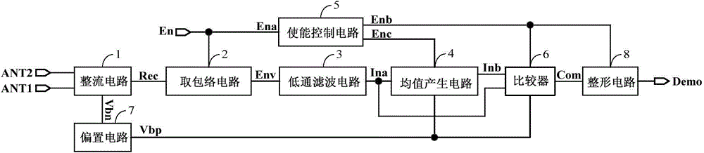
[0024] The invention belongs to the technical field of integrated circuit design and radio frequency identification, and relates to a demodulation circuit for a passive ultra-high frequency RFID tag chip. The circuit has high sensitivity, wide input range, low power consumption, small area and low cost. Features, can be applied to passive or low-power short-range wireless communication systems, such as passive UHF RFID tags.

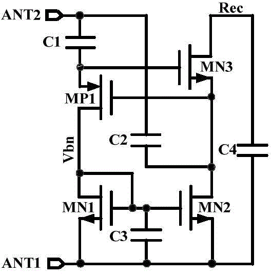
[0025] The present invention provides a demodulation circuit for passive ultra-high frequency RFID tag chips. In the demodulation circuit, rectification is realized by adopti...


PUM


Abstract

The invention discloses a demodulation circuit used for a passive ultrahigh frequency RFID label chip. The demodulation circuit comprises a rectifying circuit, an envelope extraction circuit, a low-pass filtering circuit, a mean value generating circuit, a comparator, a shaping circuit, an enabling control circuit and a biasing circuit. The rectifying circuit has a primary level and an auxiliary level, rectifying is achieved through threshold value compensation, and the envelope extraction circuit extracts envelopes under the control of the enabling control circuit. The low-pass filtering circuit is directly of an RC structure, and the mean value generating circuit is composed of an operational amplifier, a diode and a capacitor. Mean value generating is achieved based on a peak detection principle, the comparator achieves comparing through an open-loop operational amplifier, the shaping circuit is composed of two cascaded inverters, the mode that three inverters are cascaded is adopted for the enabling control circuit to control the mean value generating circuit, the comparator and the shaping circuit, so that power consumption needed when the demodulation circuit does not work is greatly lowered, and the biasing circuit provides nA-level currents for the rectifying circuit, the mean value generating circuit and the comparator. The demodulation circuit has the advantages of being high in sensitivity, large in input range, low in power consumption, small in area and low in cost.

Description

technical field [0001] The invention belongs to the technical field of radio frequency identification, and more specifically relates to a demodulation circuit for a passive ultra-high frequency RFID tag chip. Background technique [0002] With the continuous development of UHF RFID system technology, the market has higher and higher requirements for system performance. Long-distance communication, high reliability, low bit error rate, and low distortion increase the design difficulty. When the reader puts the modulated After the signal is sent to the tag, the tag receives the signal through the antenna and demodulates to obtain the baseband signal. Demodulation technology is currently divided into analog signal demodulation and digital signal demodulation, which is realized by changing the amplitude, frequency and phase of the carrier signal. The demodulation method can use synchronous detection method and envelope detection method. The principle of synchronous detection me...

Claims


Application Information

Patent Timeline
IPC IPC(8): G06K19/077
Inventor 刘冬生刘子龙邹雪城郭亮沈永健王任才
Owner HUAZHONG UNIV OF SCI & TECH
Why Eureka
Try Eureka